HEATING / AIR CONDITIONING CONDENSER INSTALLATION
CAUTION / NOTICE / HINT
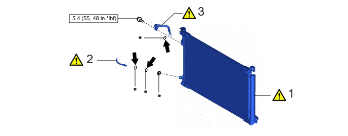
| Procedure | Part Name Code | 
|

|

|
|
|---|---|---|---|---|---|
| 1 | COOLER CONDENSER ASSEMBLY | 884A0 | ( 202307,999999,_58,_104612,_0500013,RM100000002BK1L_01_0104,) 202307,999999,_58,_104612,_0500013,RM100000002BK1L_01_0104,)
|
- | - |
| 2 | AIR CONDITIONING TUBE AND ACCESSORY ASSEMBLY | 88710E | (202307,999999,_58,_104612,_0500013,RM100000002BK1L_01_0114,)
|
- | - |
| 3 | DISCHARGE HOSE SUB-ASSEMBLY | 88703 | (202307,999999,_58,_104612,_0500013,RM100000002BK1L_01_0115,)
|
- | - |

|
N*m (kgf*cm, ft.*lbf): Specified torque | ● | Non-reusable part |

|
for Gasoline Model:
Compressor oil ND-OIL 8 or equivalent for HEV Model: Compressor oil ND-OIL 11 or equivalent |
- | - |
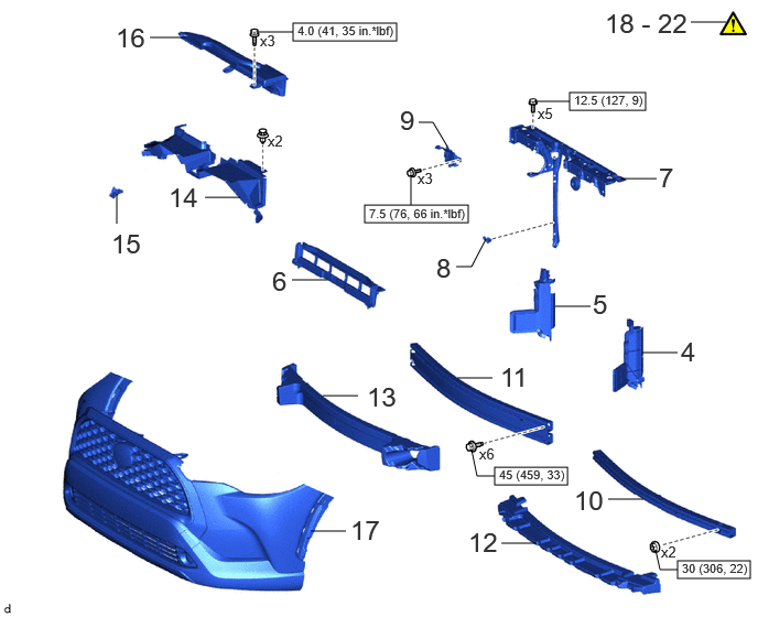
| Procedure | Part Name Code |
|
|
|
|
|---|---|---|---|---|---|
| 4 | NO. 1 RADIATOR AIR GUIDE LH | 16595D | - | - | - |
| 5 | NO. 1 RADIATOR AIR GUIDE RH | 16593D | - | - | - |
| 6 | NO. 2 RADIATOR AIR GUIDE | 16594A | - | - | - |
| 7 | UPPER RADIATOR SUPPORT SUB-ASSEMBLY WITH HOOD LOCK SUPPORT SUB-ASSEMBLY | - | - | - | - |
| 8 | THERMISTOR ASSEMBLY | 88790B | - | - | - |
| 9 | HOOD LOCK ASSEMBLY WITH COURTESY LIGHT SWITCH | 53510G | - | - | - |
| 10 | NO. 2 FRONT BUMPER REINFORCEMENT | 52132A | - | - | - |
| 11 | FRONT BUMPER REINFORCEMENT SUB-ASSEMBLY | 52021 | - | - | - |
| 12 | FRONT BUMPER LOWER ABSORBER | 52618 | - | - | - |
| 13 | FRONT BUMPER ENERGY ABSORBER | 52611 | - | - | - |
| 14 | NO. 1 RADIATOR TO SUPPORT SEAL | 16561C | - | - | - |
| 15 | LOWER NO. 2 FRONT BUMPER RETAINER | 52527C | - | - | - |
| 16 | INLET NO. 1 AIR CLEANER | 17751 | - | - | - |
| 17 | FRONT BUMPER ASSEMBLY | - | - | - | - |
| 18 | CHARGE AIR CONDITIONING SYSTEM WITH REFRIGERANT | - | (202307,999999,_58,_104612,_0500013,RM100000002BK1L_01_0090,)
|
- | - |
| 19 | WARM UP ENGINE | - | (202307,999999,_58,_104612,_0500013,RM100000002BK1L_01_0091,)
|
- | - |
| 20 | WARM UP COMPRESSOR | - | (202307,999999,_58,_104612,_0500013,RM100000002BK1L_01_0168,)
|
- | - |
| 21 | INSPECT FOR REFRIGERANT LEAK | - | (202307,999999,_58,_104612,_0500013,RM100000002BK1L_01_0092,)
|
- | - |
| 22 | ADJUST HOOD SUB-ASSEMBLY | - | (202307,999999,_58,_104612,_0500013,RM100000002BK1L_01_0035,)
|
- | - |
|
|
N*m (kgf*cm, ft.*lbf): Specified torque | - | - |
PROCEDURE

 884A0
1.INSTALL COOLER CONDENSER ASSEMBLY
884A0
1.INSTALL COOLER CONDENSER ASSEMBLY
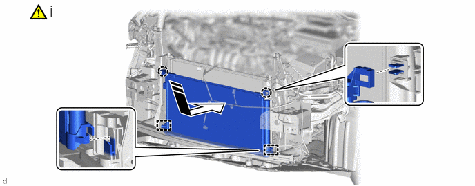

|
Install in this Direction | - | - |
Engage the guides and claws to install the cooler condenser assembly as shown in the illustration.
- NOTICE:
-
Do not damage the cooler condenser assembly or radiator assembly when installing the cooler condenser assembly.
- HINT:
-
If a new cooler condenser assembly is installed, add compressor oil to the cooler condenser assembly as follows.
- Capacity:
Add 40 cc (1.35 fl. oz)
- Compressor Oil:
- for Gasoline Model:
ND-OIL 8 or equivalent
- for HEV Model:
ND-OIL 11 or equivalent
88710E
2.CONNECT AIR CONDITIONING TUBE AND ACCESSORY ASSEMBLY
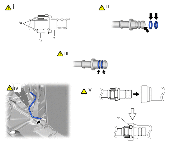
| *1 | Air Conditioning Tube and Accessory Assembly | *2 | Piping Clamp |
| *a | Groove | *b | Large Diameter Section of Piping Clamp |
Remove the vinyl tape from the cooler condenser assembly and air conditioning tube and accessory assembly and install a new piping clamp to the air conditioning tube and accessory assembly.
- NOTICE:
- ·
Securely engage the piping clamp to the groove of the air conditioning tube and accessory assembly.
·Do not open the piping clamp more than the diameter of the air conditioning tube and accessory assembly when installing it.
·Do not install the piping clamp with the large diameter section facing the wrong direction.
Sufficiently apply compressor oil to 2 new O-rings and the fitting surfaces of the air conditioning tube and accessory assembly.
- Compressor Oil:
- for Gasoline Model:
ND-OIL 8 or equivalent
- for HEV Model:
ND-OIL 11 or equivalent
Install the 2 O-rings to the air conditioning tube and accessory assembly.
- NOTICE:
-
Keep the O-rings and O-ring fitting surfaces free from foreign matter.
Connect the air conditioning tube and accessory assembly to the cooler condenser assembly.
- NOTICE:
-
Connect the parts by holding the pipe, not the piping clamp.
Securely insert the piping clamp to the point where the large diameter section of the piping clamp is covered by the cooler condenser assembly.
- NOTICE:
- ·
When inserting, make sure that a click sound is heard.
·Check that the air conditioning tube and accessory assembly is securely connected by pulling it.
88703
3.CONNECT DISCHARGE HOSE SUB-ASSEMBLY
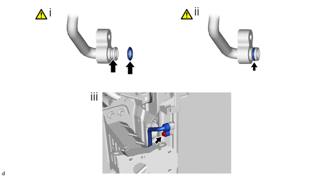
Remove the vinyl tape from the discharge hose sub-assembly and cooler condenser assembly and sufficiently apply compressor oil to a new O-ring and the fitting surface of the discharge hose sub-assembly.
- Compressor Oil:
- for Gasoline Model:
ND-OIL 8 or equivalent
- for HEV Model:
ND-OIL 11 or equivalent
Install the O-ring to the discharge hose sub-assembly.
- NOTICE:
-
Keep the O-rings and O-ring fitting surfaces free from foreign matter.
Connect the discharge hose sub-assembly to the cooler condenser assembly with the bolt.
- Torque:
- 5.4 N*m (55 kgf*cm, 48 in.*lbf)
16595D
4.INSTALL NO. 1 RADIATOR AIR GUIDE LH
16593D
5.INSTALL NO. 1 RADIATOR AIR GUIDE RH
16594A
6.INSTALL NO. 2 RADIATOR AIR GUIDE
7.INSTALL UPPER RADIATOR SUPPORT SUB-ASSEMBLY WITH HOOD LOCK SUPPORT SUB-ASSEMBLY
- Torque:
- 12.5 N*m (127 kgf*cm, 9 ft.*lbf)
88790B
8.INSTALL THERMISTOR ASSEMBLY
53510G
9.INSTALL HOOD LOCK ASSEMBLY WITH COURTESY LIGHT SWITCH
52132A
10.INSTALL NO. 2 FRONT BUMPER REINFORCEMENT
52021
11.INSTALL FRONT BUMPER REINFORCEMENT SUB-ASSEMBLY
52618
12.INSTALL FRONT BUMPER LOWER ABSORBER
52611
13.INSTALL FRONT BUMPER ENERGY ABSORBER
16561C
14.INSTALL NO. 1 RADIATOR TO SUPPORT SEAL
52527C
15.INSTALL LOWER NO. 2 FRONT BUMPER RETAINER
17751
16.INSTALL INLET NO. 1 AIR CLEANER
17.INSTALL FRONT BUMPER ASSEMBLY
18.CHARGE AIR CONDITIONING SYSTEM WITH REFRIGERANT
19.WARM UP ENGINE (for Gasoline Model)
20.WARM UP COMPRESSOR (for HEV Model)
21.INSPECT FOR REFRIGERANT LEAK
53301
22.ADJUST HOOD SUB-ASSEMBLY