RM38T0EC
_59
Vehicle Exterior
_114126
EXTERIOR PANELS / TRIM
_0505908
FRONT BUMPER(for TFTM Made)
A
EXTERIOR PANELS / TRIM FRONT BUMPER(for TFTM Made) INSTALLATION
CAUTION / NOTICE / HINT
COMPONENTS (INSTALLATION)
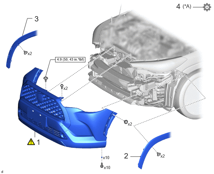
1.854,1.917 2.854,2.083
1,0.167
1.083,0.615 0.917,0.615
0.917,0.615 0.75,1.198
false
1.167,4.396 1.167,4.604
false
4.365,5.25 4.698,5.25
false
6.458,0.24 6.792,0.24
false
1.854,2 1.688,2
1.688,2 1.521,2.583
false
1.156,0.479 1.438,0.833
0.281,0.354
18
false
3
0.927,1.708 1.156,1.917
0.229,0.208
10
false
x2
2.125,2.875 2.354,3.083
0.229,0.208
10
false
x2
1.219,4.615 1.5,4.969
0.281,0.354
18
false
1
4.281,4.073 4.51,4.281
0.229,0.208
10
false
x2
3.448,5.198 3.719,5.385
0.271,0.188
10
false
x10
3.479,5.531 3.854,5.729
0.375,0.198
10
false
x10
5.375,5.146 5.604,5.354
0.229,0.208
10
false
x2
4.156,5.073 4.438,5.427
0.281,0.354
18
false
2
1.906,1.917 4.354,2.073
2.448,0.156
8
false
4.9 (50, 43 in.*lbf)
5.906,0.063 6.646,0.396
0.74,0.333
18
false
4
6.115,0.104 6.854,0.344
0.74,0.24
12
false
(*A)
| Procedure | Part Name Code | 
|

|

|
|
|---|---|---|---|---|---|
| 1 | FRONT BUMPER ASSEMBLY | - | ( 202307,999999,_59,_114126,_0505908,RM100000002CTHB_01_0076,) 202307,999999,_59,_114126,_0505908,RM100000002CTHB_01_0076,)
|
- | - |
| 2 | FRONT FENDER MOULDING SUB-ASSEMBLY LH | 75602A | - | - | - |
| 3 | FRONT FENDER MOULDING SUB-ASSEMBLY RH | 75601A | - | - | - |
| 4 | PERFORM CALIBRATION | - | - | - | (202307,999999,_59,_114126,_0505908,RM100000002CTHB_01_0080,)
|
| *A | w/ Panoramic View Monitor System | - | - |

|
N*m (kgf*cm, ft.*lbf): Specified torque | - | - |
PROCEDURE

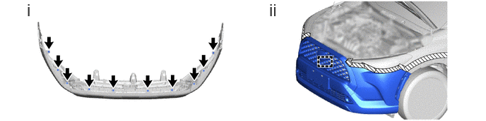
 1.INSTALL FRONT BUMPER ASSEMBLY
a.
0.396,0 0.677,0.354
0.281,0.354
18
false
i
3.969,0 4.25,0.354
0.281,0.354
18
false
ii
i.
Install the 10 grommets.
ii.
Engage the guide to temporarily install the front bumper assembly.
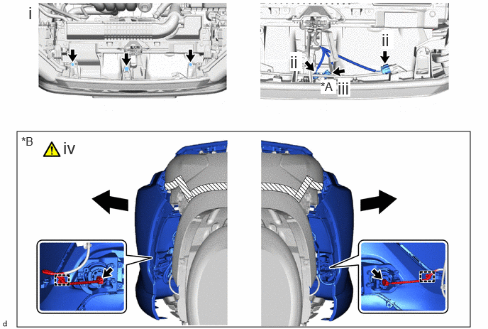
b.
0.25,1.927 6.906,4.792
6.656,2.865
0.313,1.969 0.646,2.24
0.333,0.271
12
false
*B
0.417,0.042 0.583,0.313
0.167,0.271
18
false
i
4.26,0.76 4.438,1.042
0.177,0.281
18
true
ii
0.927,2.021 1.156,2.323
0.229,0.302
18
false
iv
5.604,0.438 5.781,0.719
0.177,0.281
18
true
ii
4.958,1.146 5.146,1.417
0.188,0.271
18
true
iii
4.708,1.167 4.938,1.375
0.229,0.208
12
true
*A
| *A | w/ Panoramic View Monitor System | *B | w/ Fog Light |

|
Pull | - | - |
i.
Install the 2 screws and bolt.
- Torque:
- Bolt : 4.9 N*m (50 kgf*cm, 43 in.*lbf)
ii.
Connect the 2 connectors.
iii.
w/ Panoramic View Monitor System:
1. Connect the connector.
iv.
w/ Fog Light:
1. Pull back the side of the front bumper assembly.
- NOTICE:
-
Do not apply excessive force when pulling back the front bumper assembly.
2. Engage the clamps and connect the 2 connectors.
c.
0.417,0 0.625,0.323
0.208,0.323
18
false
i
0.406,1.896 0.615,2.219
0.208,0.323
18
false
ii

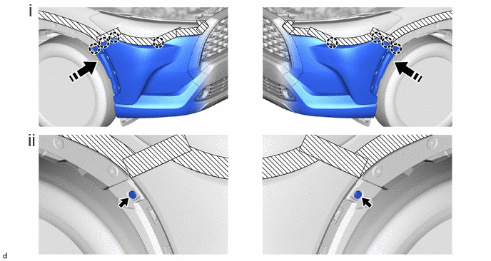
|
Install in this Direction | - | - |
i.
Engage the claws as shown in the illustration.
ii.
Install the 2 clips.
d.

2.188,0.229 2.469,0.583
0.281,0.354
18
false
i
0.354,1.885 0.635,2.24
0.281,0.354
18
false
ii
i.
Install the 10 screws.
ii.
Remove the protective tape.
75602A
2.INSTALL FRONT FENDER MOULDING SUB-ASSEMBLY LH
75601A
3.INSTALL FRONT FENDER MOULDING SUB-ASSEMBLY RH
4.PERFORM CALIBRATION (w/ Panoramic View Monitor System)