EXTERIOR PANELS / TRIM FRONT BUMPER(for GTMC Made) INSTALLATION
CAUTION / NOTICE / HINT
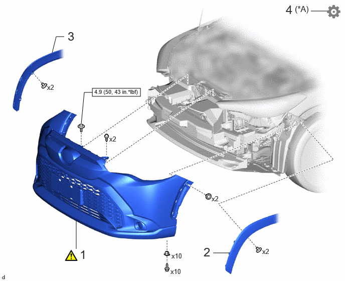
| Procedure | Part Name Code | 
|

|

|
|
|---|---|---|---|---|---|
| 1 | FRONT BUMPER ASSEMBLY | - | ( 202307,999999,_59,_114126,_0505910,RM100000002CTHD_01_0076,) 202307,999999,_59,_114126,_0505910,RM100000002CTHD_01_0076,)
|
- | - |
| 2 | FRONT FENDER MOULDING SUB-ASSEMBLY LH | 75602A | - | - | - |
| 3 | FRONT FENDER MOULDING SUB-ASSEMBLY RH | 75601A | - | - | - |
| 4 | PERFORM CALIBRATION | - | - | - | (202307,999999,_59,_114126,_0505910,RM100000002CTHD_01_0080,)
|
| *A | w/ Panoramic View Monitor System | - | - |

|
N*m (kgf*cm, ft.*lbf): Specified torque | - | - |
PROCEDURE

 1.INSTALL FRONT BUMPER ASSEMBLY
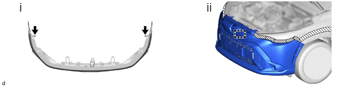
Install the 10 grommets.
Engage the guide to temporarily install the front bumper assembly.
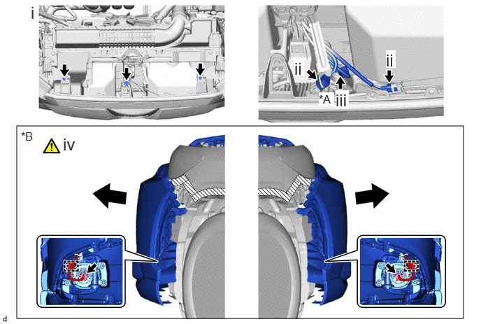
| *A | w/ Panoramic View Monitor System | *B | w/ Fog Light |

|
Pull | - | - |
Install the 2 screws and bolt.
- Torque:
- Bolt : 4.9 N*m (50 kgf*cm, 43 in.*lbf)
Connect the 2 connectors.
w/ Panoramic View Monitor System:
1. Connect the connector.
w/ Fog Light:
1. Pull back the side of the front bumper assembly as shown in the illustration.
- NOTICE:
-
Do not apply excessive force when pulling back the front bumper assembly.
2. Engage the clamps and connect the 2 connectors.
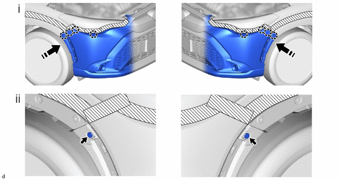

|
Install in this Direction | - | - |
Engage the claws as shown in the illustration.
Install the 2 clips.

Install the 10 screws.
Remove the protective tape.
75602A
2.INSTALL FRONT FENDER MOULDING SUB-ASSEMBLY LH
75601A
3.INSTALL FRONT FENDER MOULDING SUB-ASSEMBLY RH
4.PERFORM CALIBRATION (w/ Panoramic View Monitor System)