ADVANCED DRIVER ASSISTANCE SYSTEM UTILITY(Production Date from 2023/04) SOFTWARE UPDATE
CAUTION / NOTICE / HINT
- HINT:
-
After replacing the forward recognition camera due to a system malfunction, make sure to perform "Software Update".
The software of the forward recognition camera is always updated to the latest software via wireless communication using the communication module (DCM) or by wired communication at the dealer.
| Operation | Details |
|---|---|
| OTA reprogramming | Software update is performed after connection to DCM by CAN and wireless communication is established with the reprogramming software distribution center via DCM. |
| Wired reprogramming | Software update is performed after being connected to a service tool via CAN communication. |
PROCEDURE

 1. PREPARATION WORK
- NOTICE:
-
If the voltage drops or fluctuates as an individual system or electric fan is activated during wired reprogramming, it becomes impossible to write the software, potentially damaging the ECU.
Electrical load reduction
Turn off all the systems that can be stopped and have an electrical load.
- HINT:
- ·
Exterior lights
·Interior lights (turn off so that they do not come on even if a door is opened)
·Air conditioning system
·Audio/navigation system
·Seat belt warning (belt lock)
·Retrofitted equipment, etc.
·Other commercially available electrical components (remote starter, security, etc.)
Remove the electric fan fuse or relay.
Auxiliary battery voltage inspection
Turn the ignition switch to ON (IG) and wait for 1 minute.
- Standard Voltage:
11.8 V or higher
If the auxiliary battery voltage is below 11.8 V, recharge or replace the auxiliary battery.
Connection of a battery charger and auxiliary charging battery to the auxiliary battery (assistance terminal)
- NOTICE:
-
If the No. 2 skid control ECU (brake actuator assembly) of the HEV model is activated, a large current flows and wired reprogramming becomes unavailable because the drop in voltage cannot be compensated for by the battery charger alone. Therefore, in the case of the HEV model, connect not only a battery charger but also an auxiliary charging battery in parallel when performing wired reprogramming.
Check of the deterioration status of the auxiliary charging battery
Perform an inspection using a conductance-type battery tester or a load-type battery tester (which discharges 100 A for 5 seconds or more).
- HINT:
-
If any of the above battery testers is not available, remove the auxiliary battery of another vehicle (whose displacement is 2 liter (2.1 US qts, 1.8 Imp. qts) or less) and check that the engine can be started, with the auxiliary charging battery mounted. If the engine cannot be started, replace the auxiliary charging battery.
-
(This is to check that there is no short circuit in the auxiliary charging battery.)
If the inspection result of the auxiliary charging battery is not OK, replace the auxiliary charging battery.
Check of the charging status of the auxiliary charging battery
Inspect the open circuit voltage of the auxiliary charging battery (when not connected).
- Standard Voltage:
12.6 V or higher
If the voltage of the auxiliary charging battery is below 12.6 V, recharge or replace the auxiliary charging battery.
Installation of the battery terminal attachment set
- NOTICE:
-
When not in use, remove the battery terminal attachment set from the auxiliary charging battery and store it. Keeping the battery terminal attachment set attached can cause a short circuit.
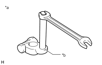
| *a | Battery terminal attachment set |
| *b | Check for looseness. |
Check the bar part of the battery terminal attachment set for looseness.
Install the battery terminal attachment set to the auxiliary charging battery.
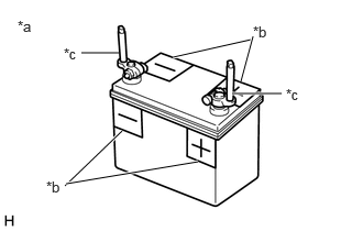
| *a | Auxiliary charging battery |
| *b | Positive (+) and negative (-) labels for wrong connection prevention |
| *c | Battery terminal attachment set |
To prevent the wrong connection, put positive (+) and negative (-) labels or other markings on the auxiliary charging battery.
Connection of a battery charger, auxiliary charging battery and booster cable
- NOTICE:
- ·
When using a battery charger that requires manual current value setting, be careful not to cause overcharging.
·If the battery charger is connected to the vehicle when the power of the battery charger is on, the fuse may blow out. When connecting the battery charger to the vehicle, make sure that its power is off.
·When the vehicle has an assistance terminal, connect the positive end of the booster cable to the assistance terminal, not the positive terminal of the auxiliary battery.
Turn off the battery charger.
Connect the battery charger and auxiliary charging battery.
- NOTICE:
-
To prevent the wrong connection, connect them according to the positive (+) and negative (-) labels put on the auxiliary charging battery.
Connect the booster cable to the auxiliary charging battery.
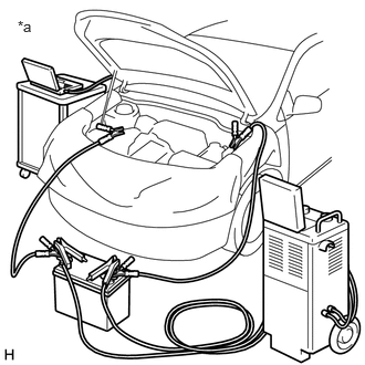
| *a | The illustration shown is an example only. |
Connect the positive end of the booster cable to the positive terminal (assistance terminal) of the auxiliary battery and the negative end to a metallic part of the uncoated vehicle.
- NOTICE:
-
Connect the battery charger, auxiliary charging battery, booster cable and vehicle in parallel.
2. COMPONENTS TO BE REPLACED
Operate the GTS to perform Health Check.
Check the DTC and perform diagnosis by following the instructions given in "How to Proceed with Troubleshooting".
If the component needs to be replaced as a result of the diagnosis, perform the following procedure.
| Target component | Reference |
|---|---|
| Forward recognition camera | 3. COMPONENT REPLACEMENT AND WIRED REPROGRAMMING |
3. COMPONENT REPLACEMENT AND WIRED REPROGRAMMING
Replace the component with a new one.
- NOTICE:
-
When replacing the component, always replace it with a new one. If a product installed to another vehicle is used, the information stored in the ECU does not match the information from the vehicle and a DTC may be stored.
- HINT:
-
For information about component replacement, refer to the removal/installation procedure of the relevant component.
Using the GTS, check if a software update is necessary, and perform a wired software update as necessary.
Refer to Service Bulletin for information about ECU program rewriting.
When the forward recognition camera has been replaced with a new one, it is necessary to perform optical axis alignment for the forward recognition camera.
- HINT:
-
Forward recognition camera beam axis alignment can be performed by using "One Time Recognition", "Driving Adjustment" or "Camera Axis Adjustment Value Write".
- ···
Camera Axis Adjustment Value Write:
Turn the ignition switch to ON (IG), wait for 5 minutes, then confirm that the following notification is not displayed on the multi-information display.
| Multi-information display |
|---|
| System Malfunction Visit Your Dealer |