ADVANCED DRIVER ASSISTANCE SYSTEM FRONT CAMERA(Production Date from 2023/04) TARGET ADJUSTMENT(ONE TIME RECOGNITION)
CAUTION / NOTICE / HINT
- NOTICE:
-
Make sure to read Before Starting Adjustment before proceeding with work.
PROCEDURE

 1. SECURE APPROPRIATE AREA FOR PERFORMING LEARNING
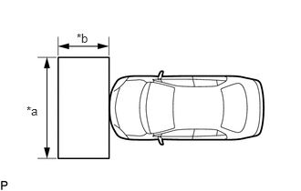
| *a | 2 m (6.56 ft.) |
| *b | 1 m (3.28 ft.) |
Park the vehicle on a level surface.
- HINT:
- ·
Make sure that the target recognition area of the forward recognition camera is free of objects which may be misrecognized as a target, such as overhead lights, windows, reflective objects, etc.
·If there are any objects which may be misrecognized as a target behind the area where a target will be placed, prepare an appropriate object to block the background.
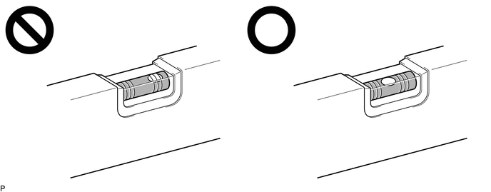
Check the levelness of the ground.


|
Levelness Check Point |
Check the levelness of the ground at the 2 points shown in the illustration.
Place the level on each levelness check point and check that the air bubble of the level is centered.
Adjust the tire inflation pressure to the specified pressure.
Clean the windshield glass.
2. CREATE TARGET
When using a target SST or previously created target:
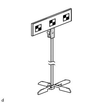
Prepare the SST.
- SST
- 09870-60000 09870-60060 09870-61100 09870-62200 (09870-60010, 09870-60020)
When not using a target SST or previously created target:
- NOTICE:
-
Do not laminate the target or attach reflective materials, such as clear adhesive tape, to its surface. If there are reflective areas on the surface of the target, they will appear white to the forward recognition camera and the target may not be recognized.
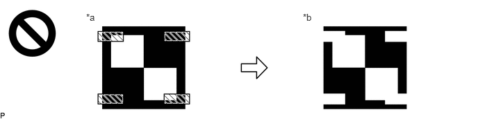 4.542,0.177 4.917,0.417 0.375,0.24 10 false *b 1.292,0.177 1.667,0.417 0.375,0.24 10 false *a
*a Actual Target *b Target as Seen by forward recognition camera
Reflective Object or Surface - -
Print 3 copies of the illustration.

Check that the dimensions are within the values shown in the illustration.
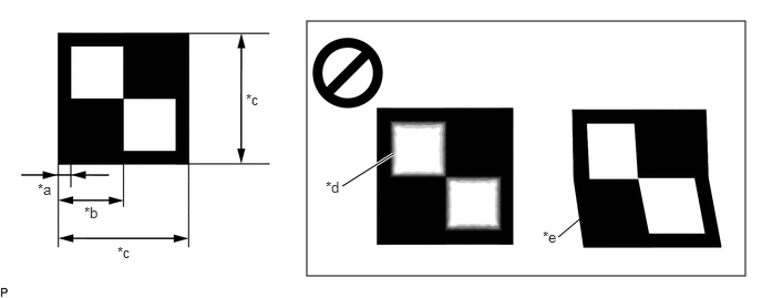
| *a | 12 mm (0.472 in.) | *b | 60 mm (2.36 in.) |
| *c | 120 mm (4.72 in.) | *d | Blurry |
| *e | Distorted | - | - |
- NOTICE:
- ·
Make sure that the black areas of the target sheet are not glossy.
·Make sure that the borders of the black and white areas on the target sheet are straight, and are not warped or blurry.
- HINT:
-
If the dimensions of the created target sheet are not within +/- 5 mm (0.197 in.) of the specified values, adjust the printer settings and reprint the target sheet so that the dimensions are as specified.
Prepare a piece of cardboard and draw lines on it as shown in the illustration.
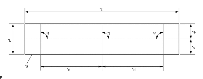
| *a | Cardboard | *b | 130 mm (5.12 in.) or more |
| *c | 730 mm (2.39 ft.) or more | *d | 297 mm (11.69 in.) |
| *e | 65 mm (2.56 in.) or more | *f | 90° |
Place the 3 target sheets on the cardboard with the black area of each at the top right and align the borders of the black and white areas with the lines as shown in the illustration.
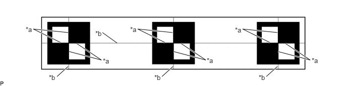
| *a | Border of Black and White Area | *b | Line |
Securely attach the target sheets to the cardboard using double-sided tape.
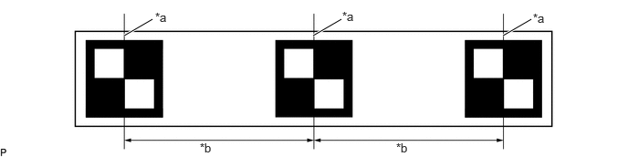
| *a | Border of Black and White Area | *b | 297 mm (11.69 in.) +/- 3 mm (0.12 in.) |
- NOTICE:
-
Do not attach reflective materials, such as clear adhesive tape, to the target sheet surface as this may affect target recognition.
Remove SST (reflector) from SST (base stand).
- SST
- 09870-60000 (09870-60010, 09870-60020)
Align the center of the target sheet with SST (reflector) and attach the target to SST (reflector) with double-sided tape.
Install SST (reflector) to SST (base stand).
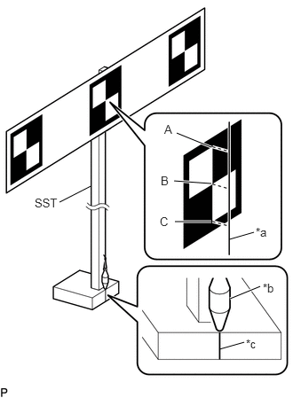
| *a | String |
| *b | Weight |
| *c | Mark-off Line |
Hang a weight with a pointed tip from the top center of the target sheet and align it with the mark-off line of SST (base stand) as shown in the illustration.
- HINT:
- ·
Make sure that the points (A), (B) and (C) of the target sheet are aligned with the string.
·As SST may fall forward, make sure to place a weight on the base of SST.
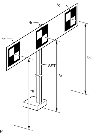
| *a | 1350 mm (53.15 in.) |
| *b | Center target |
| *c | Left target |
| *d | Right target |
Move SST (reflector) up or down so that the center of the 3 target sheets is at the height shown in the illustration, and secure SST (reflector) in place.
- HINT:
- ·
The permissible range of the target height should be +/-5 mm. If the target height is outside the permissible range, adjust it until it is within that range.
·To prevent the targets from tilting, the difference between the left target height and right target height should be within 5 mm. If the difference is outside the permissible range, adjust it until it is within that range.
Prepare an object to block the area behind the target. (If there are any objects which may be misrecognized as a target behind the area where a target will be placed.)
When blocking the background by holding cardboard behind the target:
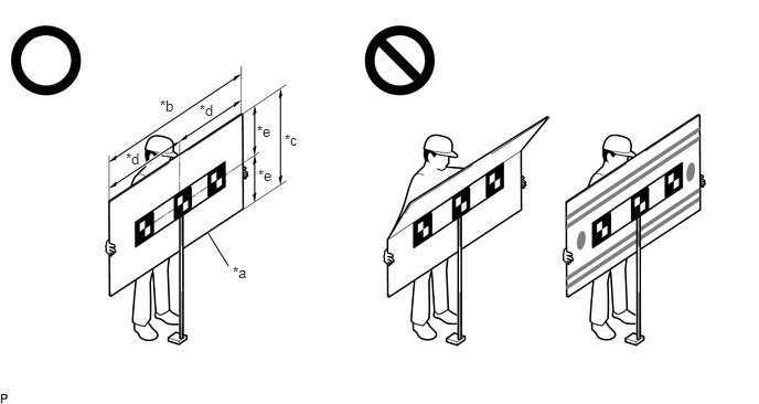
| *a | Cardboard | *b | 1160 mm (3.80 ft.) or more |
| *c | 560 mm (1.84 ft.) or more | *d | 580 mm (1.90 ft.) or more |
| *e | 280 mm (0.918 ft.) or more | - | - |
Prepare a piece of cardboard with the dimensions shown in the illustration.
- HINT:
- ·
Do not use cardboard that is bent or has a pattern or image on it.
·Do not use cardboard which has a reflective surface or reflective objects attached to it.
·Make sure to hold the cardboard in such a way that fingers are not within the target recognition area.
When blocking the background using a light colored plain cloth:
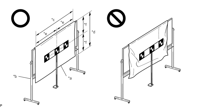
| *a | Light Colored Plain Cloth | *b | Whiteboard or Equivalent |
| *c | 1160 mm (3.80 ft.) or more | *d | 560 mm (1.84 ft.) or more |
| *e | 580 mm (1.90 ft.) or more | *f | 280 mm (0.918 ft.) or more |
Cover a whiteboard or equivalent with light colored plain cloth and secure it.
- HINT:
- ·
Make sure to stretch the cloth to remove wrinkles before securing it.
·Make sure that the target recognition area is free of clear adhesive tape, reflective surfaces and reflective objects.
3. DETERMINE TARGET PLACEMENT POSITION
Hang a weight with a pointed tip from the center of the front emblem, and mark the front center point of the vehicle (point A) on the ground (placement position).
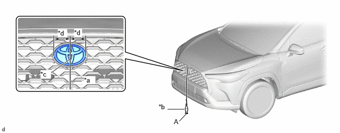
| *a | String | *b | Weight |
| *c | Center | *d | Bilateral Symmetry |
- HINT:
-
Lightly flick the string with your fingers several times to confirm that the string is perpendicular to the ground.
4. PERFORM FORWARD RECOGNITION CAMERA OPTICAL AXIS LEARNING
- NOTICE:
- ·
Close all of the doors.
·Make sure that no one is inside the vehicle.
·Do not lean on the vehicle.
·Make sure that the headlights are turned off.
·Make sure the vehicle is unloaded.
Perform Recognition Camera/Target Position Memory.
Connect the GTS to the DLC3.
Turn the ignition switch to ON.
Turn the GTS on.
Enter the following menus: Chassis / Front Recognition Camera / Utility / Recognition Camera/Target Position Memory.
- Chassis > Front Recognition Camera > Utility
-
Tester Display Recognition Camera/Target Position Memory - 50005 498 2394
Press "Next".*1
Confirm the conditions displayed on the screen and then press "Next".
According to the display on the GTS, enter the following values for each respective item.
| Item | Value |
|---|---|
| Target Height | 1350 mm (53.15 in.) |
| Target Distance | 1712 mm (67.40 in.) |
| Distance between Targets | 297 mm (11.69 in.) |
| Target Size | 120 mm (4.72 in.) |
| Pitch Offset Angle | 0 deg. |
If "Recognition Camera/Target Position Memory has failed." is displayed on the GTS screen, confirm the conditions displayed on the screen, then press "Yes" and repeat the procedure from *1.
Press "Exit" to exit the Recognition Camera/Target Position Memory utility.
Perform Recognition Camera Axis Adjust (target positioning).
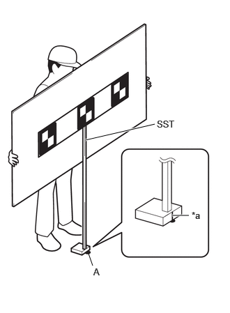
| *a | Mark-off Line |
Move the target to align the front mark-off line of SST with the placement point (point A) as shown in the illustration.
- HINT:
-
Set the target directly facing the camera, because setting the target at an angle may prevent correct optical axis learning.
 0.583,2.167 0.75,2.167 0.75,2.167 1,1.75 false 4.333,2.188 4.5,2.188 4.5,2.188 4.75,1.771 false 0.385,2.104 0.698,2.302 0.313,0.198 10 false *a 4.135,2.125 4.448,2.323 0.313,0.198 10 false *a
*a Target - -
Enter the following menus: Chassis / Front Recognition Camera / Utility / Recognition Camera Axis Adjust.
- Chassis > Front Recognition Camera > Utility
-
Tester Display Recognition Camera Axis Adjust - 50005 498 4954
Press "Next".
Check that the values stored in the ECU are correct and then press "Next".
If "Failed to read axis adjustment data" is displayed, perform Recognition Camera/Target Position Memory, and repeat the procedure from *1.
Confirm the conditions displayed on the screen and then press "Next".
Check that the target is placed at point B (placement position) and then press "Next".
- HINT:
-
If there are any objects which may be misrecognized as a target behind the area where a target will be placed, block the area behind the target with an appropriate object before pressing "Next".
Perform the adjustment according to the display on the GTS.
- NOTICE:
-
If an error code is displayed, perform troubleshooting according to the following table, then perform the adjustment again.
Error No. Error Description Cause of Error Action to be Taken 1 Target 1 (Center) malfunction ·Center target cannot be recognized
Entering the adjustment area during beam axis adjustment is prohibited (Do not allow anything to pass between the target and the vehicle) The values stored in recognition camera/target positions are correct The target height and placement points are appropriate There are no objects in the background that could be mistakenly detected as the target and the background is hidden ·There is an appropriate amount of light (brightness)
·There are no reflective objects such as cellophane tape on the target or object used to conceal the background
·The target is correctly orientated (black area positioned on top right)
·Not in a backlight condition
·The windshield glass is clean
Check the camera installation condition
(The camera is properly installed (completely installed) and has been installed after the cover is attached)2 Target 2 (Left) malfunction ·Left target cannot be recognized
Entering the adjustment area during beam axis adjustment is prohibited (Do not allow anything to pass between the target and the vehicle) The values stored in recognition camera/target positions are correct The target height and placement points are appropriate There are no objects in the background that could be mistakenly detected as the target and the background is hidden ·There is an appropriate amount of light (brightness)
·There are no reflective objects such as cellophane tape on the target or object used to conceal the background
·The target is correctly orientated (black area positioned on top right)
·Not in a backlight condition
·The windshield glass is clean
Check the camera installation condition
(The camera is properly installed (completely installed) and has been installed after the cover is attached)3 Target 3 (Right) malfunction ·Right target cannot be recognized
Entering the adjustment area during beam axis adjustment is prohibited (Do not allow anything to pass between the target and the vehicle) The values stored in recognition camera/target positions are correct The target height and placement points are appropriate There are no objects in the background that could be mistakenly detected as the target and the background is hidden ·There is an appropriate amount of light (brightness)
·There are no reflective objects such as cellophane tape on the target or object used to conceal the background
·The target is correctly orientated (black area positioned on top right)
·Not in a backlight condition
·The windshield glass is clean
Check the camera installation condition
(The camera is properly installed (completely installed) and has been installed after the cover is attached)·1 and 4 displayed simultaneously
·2 and 4 displayed simultaneously
·3 and 4 displayed simultaneously
Target stuck malfunction ·SST (target) shaking during beam axis adjustment
·Vehicle shaking during beam axis adjustment
SST (target) does not move due to the wind, etc. Adjust the vehicle so that it does not move
·Do not enter the vehicle while beam axis adjustment is in progress
·Do not lean on the vehicle during beam axis adjustment
There are no objects in the background that could be mistakenly detected as the target and the background is hidden 5 Target position and interval malfunction ·Detected target position and interval is incorrect
The target height and placement points are appropriate There are no objects in the background that could be mistakenly detected as the target and the background is hidden 9 FOE and role angle malfunction ·Calculated parameter values are incorrect
The target height and placement points are appropriate (The levelness of the placement area is within the specified value. (See page 1. SECURE APPROPRIATE AREA FOR PERFORMING LEARNING)) The values stored in recognition camera/target positions are correct The camera is installed correctly (The camera is properly installed (completely installed) and has been installed after the cover is attached)
Press "Exit" to exit the Recognition Camera Axis Adjust utility.
Turn the ignition switch off.
Disconnect the GTS from the DLC3.
Forward recognition camera optical axis learning is complete.
After optical axis adjustment completes, clear the following system vehicle control history entries.
Clear vehicle control history (Front Camera System).
Clear vehicle control history (Automatic High Beam System).