NAVIGATION / MULTI INFO DISPLAY NAVIGATION SYSTEM(Production Date from 2023/04) TERMINALS OF ECU
RADIO AND DISPLAY RECEIVER ASSEMBLY
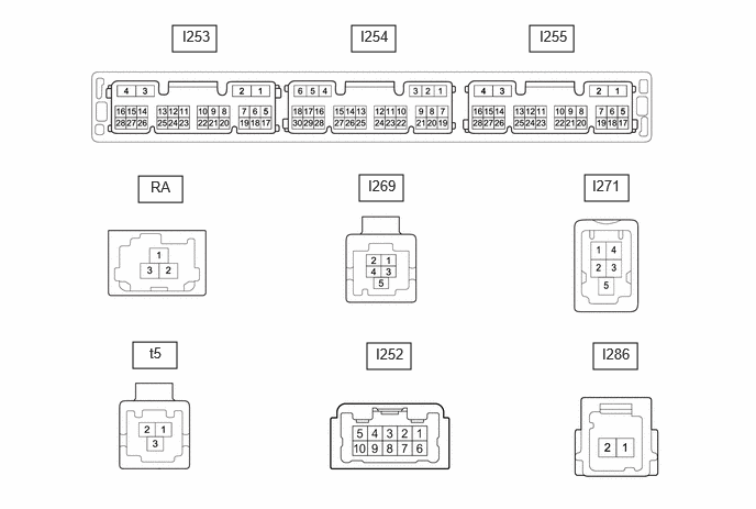
- Standard:
Connector I253 Terminal No. (Symbol) Terminal Description Condition Specified Condition *1: w/ Panoramic View Monitor System
*2: w/ Parking Assist Monitor System
I253-1 (GND1) - Body ground Ground Always Below 1 Ω I253-2 (GND2) - Body ground Ground Always Below 1 Ω I253-3 (+B) - I253-1 (GND1) No. 1 stereo jack adapter assembly power source Ignition switch off 11 to 14 V I253-4 (+B1) - I253-1 (GND1) Power source (+B) Ignition switch off 11 to 14 V I253-5 (REV) - I253-1 (GND1) Reverse Signal Ignition switch ON, shift position not in R → shift position in R 2 V or less → 11 to 14 V I253-7 (PKB) - I253-1 (GND1) Parking brake signal Ignition switch ON Parking brake released → Ignition switch ON Parking brake applied 2 V or less → 3 V or higher I253-8 (SPD) - I253-1 (GND1) Vehicle speed signal Wheel being rotated Waveform 1 I253-15 (IG) - I253-1 (GND1) Power source (IG) Ignition switch ON 11 to 14 V I253-16 (ACC1) - I253-1 (GND1) Power source (ACC) Ignition switch ACC 11 to 14 V I253-17 (REVD) - I253-1 (GND1)*2 Camera image transition signal Normal → camera image screen change 2 V or less → 6 V or higher I253-18 (CSWA) - I253-1 (GND1)*1 Camera image transition signal Normal → camera image screen change 2 V or less → 6 V or higher I253-19 (CSW) - I253-1 (GND1)*1 Camera image transition signal Normal → camera image screen change 2 V or less → 6 V or higher I253-20 (SWG) - I253-1 (GND1) Ground Always Below 1 Ω I253-21 (SW1) - I253-1 (GND1) Steering pad switch signal No switch pushed → Volume- switch pushed → Volume+ switch pushed → Seek- switch pushed → Seek+ switch pushed 2.7 V or higher → approximately 2.3 V → approximately 1.6 V → approximately 1.0 V → 0.8 V or less I253-22 (SW2) - I253-1 (GND1) Steering pad switch signal No switch pushed → Voice switch pushed → Off hook switch pushed → On hook switch pushed → MODE switch pushed 2.7 V or higher → approximately 2.3 V → approximately 1.6 V → approximately 1.0 V → 0.8 V or less I253-25 (ILL+) - I253-1 (GND1) Illumination signal Light control switch not in tail or head position 11 to 14 V I253-28 (ACCO) - I253-1 (GND1) Multimedia ACC control signal Power switch is pressed when playback is starting 8.0 to 13.5 V
Connector I254 Terminal No. (Symbol) Terminal Description Condition Specified Condition *1: w/ Parking Assist Monitor System
I254-4 (SGND) - I253-1 (GND1) Shield ground Always Below 1 Ω I254-5 (TMUT) - I253-1 (GND1) Mute signal Normal → Emergency call mode 2.0 V or higher → Below 1 V I254-6 (ADPG) - I253-1 (GND1) No. 1 stereo jack adapter assembly detection signal No. 1 stereoo jack adapter assembly disconnected → No. 1 stereo jack adapter assembly connected 2 V or less → 6 V or higher I254-11 (CNH1) Local bus communication signal Service Menu - I254-12 (CNL1) Local bus communication signal Service Menu - I254-13 (CANH) CAN communication signal Service Menu - I254-14 (CANL) CAN communication signal Service Menu - I254-15 (VOR+) - I253-1 (GND1) Sound signal Answering incoming operator call A waveform synchronized with sound signals is output I254-16 (VOR-) - I253-1 (GND1) Sound signal Answering incoming operator call A waveform synchronized with sound signals is output I254-17 (USBG) - Body ground Ground Always Below 1 Ω I254-18 (USBV) - I253-1 (GND1) Telematics transceiver USB power source Ignition switch ON 3 V or higher I254-21 (MIN+) - I253-1 (GND1) Microphone voice signal Voice is being input A waveform synchronized with sound signals is output I254-22 (MIN-) - I253-1 (GND1) Microphone voice signal ground Always Below 1 Ω I254-24 (SGND) - Body ground Shield ground Always Below 1 Ω I254-25 (SNS) - I253-1 (GND1) Microphone circuit open detection signal Always Below 1 Ω I254-26 (CSLD) - I253-1 (GND1)*1 Shield ground Always Below 1 Ω I254-27 (CGND) - I253-1 (GND1)*1 Ground Always Below 1 Ω I254-28 (V+) - I254-29 (V-) Video signal (analog) Ignition switch ON, shift lever in R Waveform 2 I254-29 (V-) - I253-1 (GND1) Video signal (analog) ground Always Below 1 Ω I254-30 (CA+) - I253-1 (GND1)*1 Rear television camera power source Ignition switch ON 5.8 to 6.5 V
Connector I255 Terminal No. (Symbol) Terminal Description Condition Specified Condition I255-17 (MI2+) - I253-1 (GND1) Microphone 2 voice signal Voice is being input A waveform synchronized with sound signals is output I255-18 (MI2-) - I253-1 (GND1) Microphone 2 voice signal ground Always Below 1 Ω I255-19 (SGD2) - I253-1 (GND1) Ground Always Below 1 Ω I255-20 (MAC2) - I253-1 (GND1) Microphone 2 power source Ignition switch ON 7.5 to 8.5 V I255-21 (SNS2) - I253-1 (GND1) Microphone 2 open circuit detection signal Always Below 1 Ω
Connector I252 Terminal No. (Symbol) Terminal Description Condition Specified Condition I252-1 (FR+) - I253-1 (GND1) Sound signal Audio system playing A waveform synchronized with sound signals is output I252-2 (FL+) - I253-1 (GND1) Sound signal Audio system playing A waveform synchronized with sound signals is output I252-3 (RL+) - I253-1 (GND1) Sound signal Audio system playing A waveform synchronized with sound signals is output I252-4 (RR+) - I253-1 (GND1) Sound signal Audio system playing A waveform synchronized with sound signals is output I252-6 (FR-) - I253-1 (GND1) Sound signal Audio system playing A waveform synchronized with sound signals is output I252-7 (FL-) - I253-1 (GND1) Sound signal Audio system playing A waveform synchronized with sound signals is output I252-8 (RL-) - I253-1 (GND1) Sound signal Audio system playing A waveform synchronized with sound signals is output I252-9 (RR-) - I253-1 (GND1) Sound signal Audio system playing A waveform synchronized with sound signals is output
Connector I269 (w/ Panoramic View Monitor System) Terminal No. (Symbol) Terminal Description Condition Specified Condition I269-1 (GGN4) Camera ground Always Below 1 Ω I269-2 (GVP4) Camera power source Ignition switch ON 7.5 to 9.0 V I269-3 (GV4+) Video signal - - I269-4 (GV4-) Video signal - - I269-5 (GVG4) Shield ground Always Below 1 Ω
Connector I269 (w/ Parking Assist Monitor System) Terminal No. (Symbol) Terminal Description Condition Specified Condition I269-1 (CGND) Camera ground Always Below 1 Ω I269-2 (CB+) Camera power source Ignition switch ON 7.5 to 9.0 V I269-3 (CV+) Video signal - - I269-4 (CV-) Video signal - - I269-5 (SGND) Shield ground Always Below 1 Ω
Connector I271 Terminal No. (Symbol) Terminal Description Condition Specified Condition I271-1 (USV1) Power source Ignition switch ON 4.75 to 5.25 V I271-2 (US1-) USB communication signal - - I271-3 (US1+) USB communication signal - - I271-4 (UGD1) Ground Always Below 1 Ω I271-5 (USG1) Shield ground Always Below 1 Ω
Connector t5 Terminal No. (Symbol) Terminal Description Condition Specified Condition t5-1 (USB+) USB communication signal - - t5-2 (USB-) USB communication signal - - t5-3 (USBS) Shield ground Always Below 1 Ω
Connector I286 (w/ Ethernet Communication System) Terminal No. (Symbol) Terminal Description Condition Specified Condition I286-1 (ETH-) Ethernet communication signal - - I286-2 (ETH+) Ethernet communication signal - -
Connector RA Terminal No. (Symbol) Terminal Description Condition Specified Condition RA-1 (ANT+) Radio antenna power source Receiving radio broadcast 7 to 16 V RA-2 (SUB) Radio signal (SUB) - - RA-2a (GND) Ground - - RA-3 (MAIN) Radio signal (MAIN) - - RA-3a (GND) Ground - -
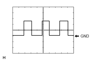
Waveform 1
| Item | Content |
|---|---|
| Measurement terminal | I253-8 (SPD) - I253-1 (GND1) |
| Measurement setting | 5 V/DIV, 20 ms/DIV |
| Condition | Wheel being rotated |
- HINT:
-
The period changes depending on the rotation speed of the wheels.
Waveform 2
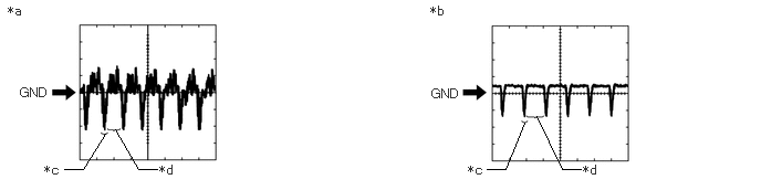
| *a | Waveform A | *b | Waveform B |
| *c | Synchronization Signal | *d | Video Waveform |
| Item | Content |
|---|---|
| Measurement terminal | I254-28 (V+) - I254-29 (V-) |
| Measurement setting | 0.2 V/DIV, 50 μS/DIV |
| Condition | ·
Waveform A: Rear television camera assembly not covered, ignition switch ON, shift lever in R and image of the area behind the vehicle being displayed ·
Waveform B: Rear television camera assembly covered by hand etc., ignition switch ON, shift lever in R and black screen being displayed |
- NOTICE:
- ·
The video waveform changes according to the image sent by the rear television camera assembly.
·The video waveform is constantly output when the ignition switch is turned to ACC.
COMBINATION METER ASSEMBLY
TELEMATICS TRANSCEIVER