NAVIGATION / MULTI INFO DISPLAY NAVIGATION SYSTEM(Production Date from 2023/04) B154913 Voice Recognition Microphone2 Circuit Open
DESCRIPTION
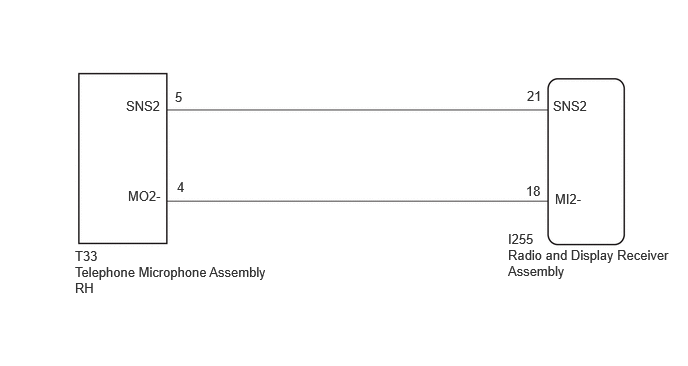
The telephone microphone assembly RH is connected to the radio and display receiver assembly via voice recognition microphone 2 signal detection line.
This DTC is stored when the radio and display receiver assembly detects disconnection of telephone microphone assembly RH.
| DTC No. | Detection Item | DTC Detection Condition | Trouble Area | DTC Output from | Priority |
|---|---|---|---|---|---|
| B154913 | Voice Recognition Microphone2 Circuit Open | Voice recognition microphone 2 terminal (SNS2) disconnected
(2 trip detection logic) |
·
Telephone microphone assembly RH ·
Radio and display receiver assembly ·
Harness or connector |
Navigation System | A |
WIRING DIAGRAM
CAUTION / NOTICE / HINT
- NOTICE:
-
Depending on the parts that are replaced during vehicle inspection or maintenance, performing initialization, registration or calibration may be needed.
PROCEDURE
Pre-procedure1
Disconnect the I255 radio and display receiver assembly connector.
Disconnect the T33 telephone microphone assembly RH connector.
Procedure1
Measure the resistance according to the value(s) in the table below.
- Standard Resistance:
Tester Connection Condition Specified Condition T33-5 (SNS2) - I255-21 (SNS2) Always Below 1 Ω T33-4 (MO2-) - I255-18 (MI2-) Always Below 1 Ω T33-5 (SNS2) - Body ground Always 10 kΩ or higher T33-4 (MO2-) - Body ground Always 10 kΩ or higher
- Result:
Proceed to OK NG
Post-procedure1
None
OK
NG
Pre-procedure1
With the radio and display receiver assembly connectors connected, disconnect the T33 telephone microphone assembly RH connector.
Procedure1
Measure the resistance according to the value(s) in the table below.
- Standard Resistance:
Tester Connection Condition Specified Condition T33-4 (MO2-) - Body ground Always Below 1 Ω
- Result:
Proceed to OK NG
Post-procedure1
None
OK
NG
Pre-procedure1
Remove the telephone microphone assembly RH.
Procedure1
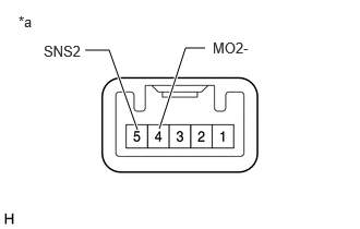
| *a | Component without harness connected
(Telephone microphone assembly RH) |
Measure the resistance according to the value(s) in the table below.
- Standard Resistance:
Tester Connection Condition Specified Condition 5 (SNS2) - 4 (MO2-) Always Below 1 Ω
- Result:
Proceed to OK NG
Post-procedure1
None
OK
NG