PARK ASSIST / MONITORING PANORAMIC VIEW MONITOR SYSTEM(Production Date from 2023/04) C162011 Rear Camera Circuit Short to Ground
DESCRIPTION
This DTC is stored if the parking assist ECU determines that the input/output signal communication with the rear television camera assembly is abnormal.
| DTC No. | Detection Item | DTC Detection Condition | Trouble Area | DTC Output from | Priority |
|---|---|---|---|---|---|
| C162011 | Rear Camera Circuit Short to Ground | Rear television camera assembly power supply malfunction | ·
Harness or connector ·
Rear television camera assembly ·
Parking assist ECU |
Circumference Monitoring Camera Control Module | A |
WIRING DIAGRAM
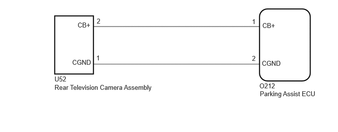
CAUTION / NOTICE / HINT
- NOTICE:
-
Depending on the parts that are replaced or operations that are performed during vehicle inspection or maintenance, calibration of other systems as well as the panoramic view monitor system may be needed.
PROCEDURE
Disconnect the O212 parking assist ECU connector.
Disconnect the U52 rear television camera assembly connector.
Measure the resistance according to the value(s) in the table below.
- Standard Resistance:
Tester Connection Condition Specified Condition O212-1 (CB+) - U52-2 (CB+) Always Below 1 Ω O212-2 (CGND) - U52-1 (CGND) Always Below 1 Ω O212-1 (CB+) or U52-2 (CB+) - Body ground Always 10 kΩ or higher O212-2 (CGND) or U52-1 (CGND) - Body ground Always 10 kΩ or higher
- Result:
Proceed to OK NG
OK
NG
Disconnect the U52 rear television camera assembly.
Measure the resistance according to the value(s) in the table below.
- Standard Resistance:
Tester Connection Condition Specified Condition U52-1 (CGND) - Body ground Always Below 1 Ω
Measure the voltage according to the value(s) in the table below.
- Standard Voltage:
Tester Connection Switch Condition Specified Condition U52-2 (CB+) - U52-1 (CGND) Ignition switch ON 7.5 to 8.5 V U52-2 (CB+) - U52-1 (CGND) Ignition switch off Below 1 V
- Result:
Proceed to OK NG
OK
NG