TELEMATICS TELEMATICS SYSTEM(for TOYOTA Connect) Telematics Transceiver Malfunction
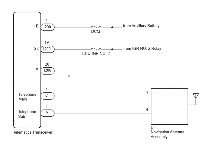
WIRING DIAGRAM
CAUTION / NOTICE / HINT
- NOTICE:
- ·
Depending on the parts that are replaced during vehicle inspection or maintenance, performing initialization, registration or calibration may be needed. Refer to Precaution for Telematics System.
·When replacing the telematics transceiver, make sure to replace it with a new one.
·Before replacing the telematics transceiver, refer to Service Bulletin.
PROCEDURE
If the vehicle is outside the communication service area, move the vehicle into a communication service area, wait for a while and perform the operation again.
- Result:
Proceed to NEXT
NEXT
Clear the DTCs.
- Body Electrical > Telematics > Clear DTCs
- 50002 459
Recheck for DTCs and check if the same DTC is output again.
- Body Electrical > Telematics > Trouble Codes
- 50001 459
- Result:
Result Proceed to No DTCs are output. A DTCs are output. B
A
B
According to the display on the GTS, read the "Data List".
- Body Electrical > Telematics > Data List
-
Tester Display Measurement Item Range Normal Condition Diagnostic Note IMEI IMEI of telematics transceiver 15 digits - - Telematics Activation Status DCM activation status Shipping or Active Shipping: Not activated
Active: Activated-
Contact the TOYOTA Connect support center.
Contact the TOYOTA Connect support center and inform them of the following:
Phenomenon: Communication has been initialized but communication is not possible.
Telematics Activation Status
IMEI
VIN
- HINT:
-
The TOYOTA Connect support center will perform an investigation and provide the results.
Check the problem symptoms after receiving a call from the TOYOTA Connect support center.
- Result:
Result Proceed to System returns to normal. A Problem symptom recurs. B
A
B
Remove the navigation antenna assembly.
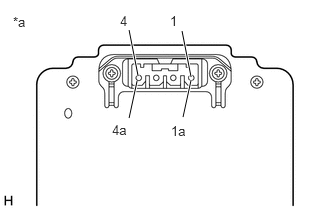
| *a | Component without harness connected
(Navigation Antenna Assembly) |
Measure the resistance according to the value(s) in the table below.
- Standard Resistance:
Tester Connection Condition Specified Condition 1 - 1a Always 4 to 11 kΩ 4 - 4a Always 4 to 11 kΩ
- Result:
Proceed to OK NG
OK
NG
- Result:
Proceed to OK NG
OK
NG
- Result:
Proceed to OK NG
OK
NG
Check for the problem symptom.
Turn the ignition switch off and then to ON.
Check if the problem symptom recurs.
- Result:
Result Proceed to System returns to normal. A System does not return to normal. B
A
B
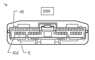
| *a | Front view of wire harness connector
(to Telematics Transceiver) |
Disconnect the telematics transceiver connector.
Measure the resistance according to the value(s) in the table below.
- Standard Resistance:
Tester Connection Condition Specified Condition I200-20 (E) - Body ground Always Below 1 Ω
Measure the voltage according to the value(s) in the table below.
- Standard Voltage:
Tester Connection Switch Condition Specified Condition I200-1 (+B) - I200-20 (E) Ignition switch off 11 to 14 V I200-19 (IG2) - I200-20 (E) Ignition switch ON 11 to 14 V
- Result:
Proceed to OK NG
OK
NG
Replace the navigation antenna assembly with a new or known good one.
- Result:
Proceed to NEXT
NEXT
Check for the problem symptom.
Turn the ignition switch off and then to ON.
Check if the problem symptom recurs.
- Result:
Result Proceed to System returns to normal. A System does not return to normal. B
A
B
Replace the telematics transceiver with a new one.
- Result:
Proceed to NEXT
NEXT