LIGHTING (EXT) LIGHTING SYSTEM LO-beam Headlight does not Illuminate
DESCRIPTION
The main body ECU (multiplex network body ECU) controls the low beam headlights.
WIRING DIAGRAM
for LED Headlight
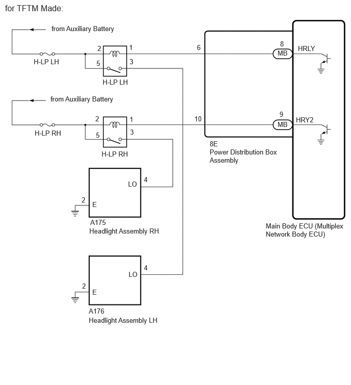
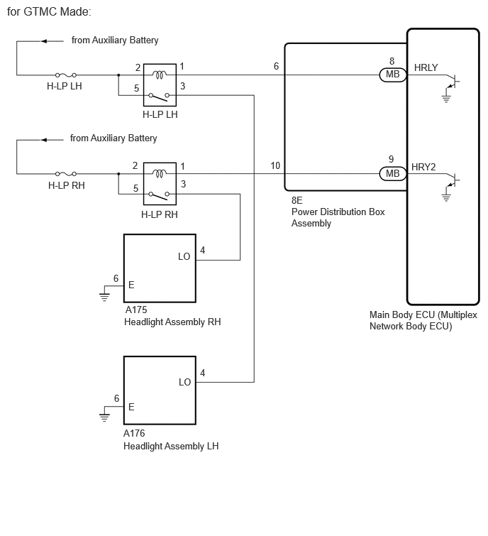
for Halogen Headlight
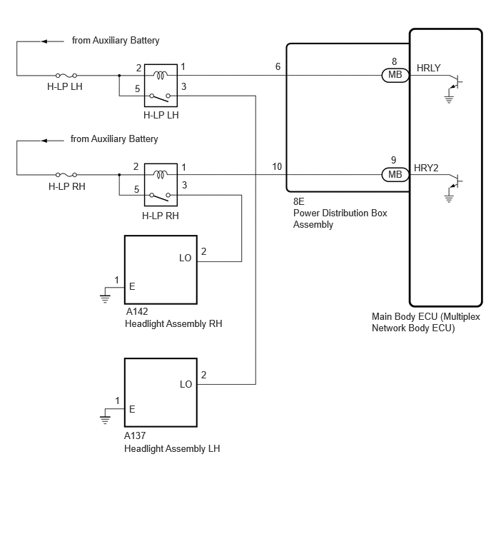
CAUTION / NOTICE / HINT
- NOTICE:
- ·
Before replacing the main body ECU (multiplex network body ECU), refer to Service Bulletin.*1
·Inspect the fuses for circuits related to this system before performing the following procedure.
*1: w/ Smart Entry and Start System
PROCEDURE
Check vehicle type.
- Result:
Result Proceed to for LED headlight A for Halogen headlight B
A
B
Enter the following menus: Body Electrical / Main Body / Active Test.
Perform the Active Test according to the display on the GTS.
- Body Electrical > Main Body > Active Test
-
Tester Display Measurement Item Control Range Diagnostic Note Headlight Relay / Light Power Supply Relay Headlights OFF or ON -
- Body Electrical > Main Body > Active Test
-
Tester Display Headlight Relay / Light Power Supply Relay - 50004 449 50
- OK:
Low beam headlights illuminate.
- Result:
Result Proceed to OK A NG (LH side low beam light does not illuminate.) (for TFTM Made) B NG (RH side low beam light does not illuminate.) (for TFTM Made) C NG (LH side low beam light does not illuminate.) (for GTMC Made) D NG (RH side low beam light does not illuminate.) (for GTMC Made) E
A
B
C
D
E
Disconnect the A176 headlight assembly LH connector.
Measure the voltage according to the value(s) in the table below.
- Standard Voltage:
Tester Connection Condition Specified Condition A176-4 (LO) - Body ground Light control switch in head position 11 to 14 V
- Result:
Proceed to OK NG
OK
NG
Measure the resistance according to the value(s) in the table below.
- Standard Resistance:
Tester Connection Condition Specified Condition A176-2 (E) - Body ground Always Below 1 Ω
- Result:
Proceed to OK NG
OK
NG
- Result:
Proceed to OK NG
OK
NG
Measure the resistance according to the value(s) in the table below.
- Standard Resistance:
Tester Connection Condition Specified Condition 3 (H-LP LH relay) - A176-4 (LO) Always Below 1 Ω 3 (H-LP LH relay) - Body ground Always 10 kΩ or higher A176-4 (LO) - Body ground Always 10 kΩ or higher
- Result:
Proceed to OK NG
OK
NG
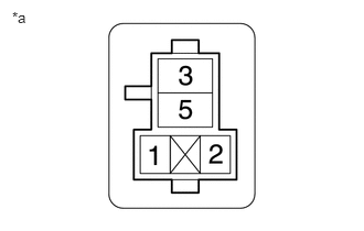
| *a | Front view of wire harness connector
(to H-LP LH Relay) |
Measure the voltage according to the value(s) in the table below.
- Standard Voltage:
Tester Connection Switch Condition Specified Condition 2 (H-LP LH relay) - Body ground Ignition switch off 11 to 14 V 5 (H-LP LH relay) - Body ground Ignition switch off 11 to 14 V
- Result:
Proceed to OK NG
OK
NG
Disconnect the 8E power distribution box assembly connector.
Measure the resistance according to the value(s) in the table below.
- Standard Resistance:
Tester Connection Condition Specified Condition 1 (H-LP LH relay) - 8E-6 Always Below 1 Ω 1 (H-LP LH relay) - Body ground Always 10 kΩ or higher 8E-6 - Body ground Always 10 kΩ or higher
- Result:
Proceed to OK NG
OK
NG
Remove the power distribution box assembly.
Remove the main body ECU (multiplex network body ECU) from the power distribution box assembly.
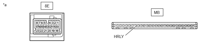
| *a | Component without harness connected
(Power Distribution Box Assembly) |
- | - |
Measure the resistance according to the value(s) in the table below.
- Standard Resistance:
Tester Connection Condition Specified Condition 8E-6 - MB-6 (HRLY) Always Below 1 Ω
- Result:
Proceed to OK NG
OK
NG
Disconnect the A175 headlight assembly RH connector.
Measure the voltage according to the value(s) in the table below.
- Standard Voltage:
Tester Connection Condition Specified Condition A175-4 (LO) - Body ground Light control switch in head position 11 to 14 V
- Result:
Proceed to OK NG
OK
NG
Measure the resistance according to the value(s) in the table below.
- Standard Resistance:
Tester Connection Condition Specified Condition A175-2 (E) - Body ground Always Below 1 Ω
- Result:
Proceed to OK NG
OK
NG
- Result:
Proceed to OK NG
OK
NG
Measure the resistance according to the value(s) in the table below.
- Standard Resistance:
Tester Connection Condition Specified Condition 3 (H-LP LH relay) - A175-4 (LO) Always Below 1 Ω 3 (H-LP LH relay) - Body ground Always 10 kΩ or higher A175-4 (LO) - Body ground Always 10 kΩ or higher
- Result:
Proceed to OK NG
OK
NG
| *a | Front view of wire harness connector
(to H-LP RH Relay) |
Measure the voltage according to the value(s) in the table below.
- Standard Voltage:
Tester Connection Switch Condition Specified Condition 2 (H-LP LH relay) - Body ground Ignition switch off 11 to 14 V 5 (H-LP LH relay) - Body ground Ignition switch off 11 to 14 V
- Result:
Proceed to OK NG
OK
NG
Disconnect the 8E power distribution box assembly connector.
Measure the resistance according to the value(s) in the table below.
- Standard Resistance:
Tester Connection Condition Specified Condition 1 (H-LP RH relay) - 8E-10 Always Below 1 Ω 1 (H-LP RH relay) - Body ground Always 10 kΩ or higher 8E-10 - Body ground Always 10 kΩ or higher
- Result:
Proceed to OK NG
OK
NG
Remove the power distribution box assembly.
Remove the main body ECU (multiplex network body ECU) from the power distribution box assembly.
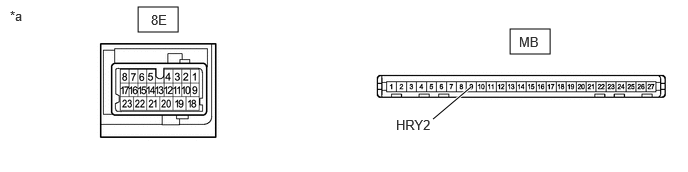
| *a | Component without harness connected
(Power Distribution Box Assembly) |
- | - |
Measure the resistance according to the value(s) in the table below.
- Standard Resistance:
Tester Connection Condition Specified Condition 8E-10 - MB-9 (HRY2) Always Below 1 Ω
- Result:
Proceed to OK NG
OK
NG
Disconnect the A176 headlight assembly LH connector.
Measure the voltage according to the value(s) in the table below.
- Standard Voltage:
Tester Connection Condition Specified Condition A176-4 (LO) - Body ground Light control switch in head position 11 to 14 V
- Result:
Proceed to OK NG
OK
NG
Measure the resistance according to the value(s) in the table below.
- Standard Resistance:
Tester Connection Condition Specified Condition A176-6 (E) - Body ground Always Below 1 Ω
- Result:
Proceed to OK NG
OK
NG
- Result:
Proceed to OK NG
OK
NG
Measure the resistance according to the value(s) in the table below.
- Standard Resistance:
Tester Connection Condition Specified Condition 3 (H-LP LH relay) - A176-4 (LO) Always Below 1 Ω 3 (H-LP LH relay) - Body ground Always 10 kΩ or higher A176-4 (LO) - Body ground Always 10 kΩ or higher
- Result:
Proceed to OK NG
OK
NG
| *a | Front view of wire harness connector
(to H-LP LH Relay) |
Measure the voltage according to the value(s) in the table below.
- Standard Voltage:
Tester Connection Switch Condition Specified Condition 2 (H-LP LH relay) - Body ground Ignition switch off 11 to 14 V 5 (H-LP LH relay) - Body ground Ignition switch off 11 to 14 V
- Result:
Proceed to OK NG
OK
NG
Disconnect the 8E power distribution box assembly connector.
Measure the resistance according to the value(s) in the table below.
- Standard Resistance:
Tester Connection Condition Specified Condition 1 (H-LP LH relay) - 8E-6 Always Below 1 Ω 1 (H-LP LH relay) - Body ground Always 10 kΩ or higher 8E-6 - Body ground Always 10 kΩ or higher
- Result:
Proceed to OK NG
OK
NG
Remove the power distribution box assembly.
Remove the main body ECU (multiplex network body ECU) from the power distribution box assembly.
| *a | Component without harness connected
(Power Distribution Box Assembly) |
- | - |
Measure the resistance according to the value(s) in the table below.
- Standard Resistance:
Tester Connection Condition Specified Condition 8E-6 - MB-6 (HRLY) Always Below 1 Ω
- Result:
Proceed to OK NG
OK
NG
Disconnect the A175 headlight assembly RH connector.
Measure the voltage according to the value(s) in the table below.
- Standard Voltage:
Tester Connection Condition Specified Condition A175-4 (LO) - Body ground Light control switch in head position Below 1 V
- Result:
Proceed to OK NG
OK
NG
Measure the resistance according to the value(s) in the table below.
- Standard Resistance:
Tester Connection Condition Specified Condition A175-6 (E) - Body ground Always Below 1 Ω
- Result:
Proceed to OK NG
OK
NG
- Result:
Proceed to OK NG
OK
NG
Measure the resistance according to the value(s) in the table below.
- Standard Resistance:
Tester Connection Condition Specified Condition 3 (H-LP RH relay) - A175-4 (LO) Always Below 1 Ω 3 (H-LP RH relay) - Body ground Always 10 kΩ or higher A175-4 (LO) - Body ground Always 10 kΩ or higher
- Result:
Proceed to OK NG
OK
NG
| *a | Front view of wire harness connector
(to H-LP RH Relay) |
Measure the voltage according to the value(s) in the table below.
- Standard Voltage:
Tester Connection Switch Condition Specified Condition 2 (H-LP RH relay) - Body ground Ignition switch off 11 to 14 V 5 (H-LP RH relay) - Body ground Ignition switch off 11 to 14 V
- Result:
Proceed to OK NG
OK
NG
Disconnect the 8E power distribution box assembly connector.
Measure the resistance according to the value(s) in the table below.
- Standard Resistance:
Tester Connection Condition Specified Condition 1 (H-LP RH relay) - 8E-10 Always Below 1 Ω 1 (H-LP RH relay) - Body ground Always 10 kΩ or higher 8E-10 - Body ground Always 10 kΩ or higher
- Result:
Proceed to OK NG
OK
NG
Remove the power distribution box assembly.
Remove the main body ECU (multiplex network body ECU) from the power distribution box assembly.
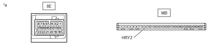
| *a | Component without harness connected
(Power Distribution Box Assembly) |
- | - |
Measure the resistance according to the value(s) in the table below.
- Standard Resistance:
Tester Connection Condition Specified Condition 8E-10 - MB-9 (HRY2) Always Below 1 Ω
- Result:
Proceed to OK NG
OK
NG
Enter the following menus: Body Electrical / Main Body / Active Test.
Perform the Active Test according to the display on the GTS.
- Body Electrical > Main Body > Active Test
-
Tester Display Measurement Item Control Range Diagnostic Note Headlight Relay / Light Power Supply Relay Headlights OFF or ON -
- Body Electrical > Main Body > Active Test
-
Tester Display Headlight Relay / Light Power Supply Relay - 50004 449 50
- OK:
Low beam headlights illuminate.
- Result:
Result Proceed to OK A NG (LH side low beam light does not illuminate.) B NG (RH side low beam light does not illuminate.) C
A
B
C
Disconnect the A137 headlight assembly LH connector.
Measure the voltage according to the value(s) in the table below.
- Standard Voltage:
Tester Connection Condition Specified Condition A137-2 (LO) - Body ground Light control switch in head position 11 to 14 V
- Result:
Proceed to OK NG
OK
NG
Measure the resistance according to the value(s) in the table below.
- Standard Resistance:
Tester Connection Condition Specified Condition A137-1 (E) - Body ground Always Below 1 Ω
- Result:
Proceed to OK NG
OK
NG
- Result:
Proceed to OK NG
OK
NG
Measure the resistance according to the value(s) in the table below.
- Standard Resistance:
Tester Connection Condition Specified Condition 3 (H-LP LH relay) - A137-2 (LO) Always Below 1 Ω 3 (H-LP LH relay) -Body ground Always 10 kΩ or higher A137-2 (LO) -Body ground Always 10 kΩ or higher
- Result:
Proceed to OK NG
OK
NG
| *a | Front view of wire harness connector
(to H-LP LH Relay) |
Measure the voltage according to the value(s) in the table below.
- Standard Voltage:
Tester Connection Switch Condition Specified Condition 2 (H-LP LH relay) - Body ground Ignition switch off 11 to 14 V 5 (H-LP LH relay) - Body ground Ignition switch off 11 to 14 V
- Result:
Proceed to OK NG
OK
NG
Disconnect the 8E power distribution box assembly connector.
Measure the resistance according to the value(s) in the table below.
- Standard Resistance:
Tester Connection Condition Specified Condition 1 (H-LP LH relay) - 8E-6 Always Below 1 Ω 1 (H-LP LH relay) - Body ground Always 10 kΩ or higher 8E-6 - Body ground Always 10 kΩ or higher
- Result:
Proceed to OK NG
OK
NG
Remove the power distribution box assembly.
Remove the main body ECU (multiplex network body ECU) from the power distribution box assembly.
| *a | Component without harness connected
(Power Distribution Box Assembly) |
- | - |
Measure the resistance according to the value(s) in the table below.
- Standard Resistance:
Tester Connection Condition Specified Condition 8E-6 - MB-8 (HRLY) Always Below 1 Ω
- Result:
Proceed to OK NG
OK
NG
Disconnect the A142 headlight assembly RH connector.
Measure the voltage according to the value(s) in the table below.
- Standard Voltage:
Tester Connection Condition Specified Condition A142-2 (LO) - Body ground Light control switch in head position 11 to 14 V
- Result:
Proceed to OK NG
OK
NG
Measure the resistance according to the value(s) in the table below.
- Standard Resistance:
Tester Connection Condition Specified Condition A142-1 (E) - Body ground Always Below 1 Ω
- Result:
Proceed to OK NG
OK
NG
- Result:
Proceed to OK NG
OK
NG
Measure the resistance according to the value(s) in the table below.
- Standard Resistance:
Tester Connection Condition Specified Condition 3 (H-LP RH relay) - A142-2 (LO) Always Below 1 Ω 3 (H-LP RH relay) - Body ground Always 10 kΩ or higher A142-2 (LO) - Body ground Always 10 kΩ or higher
- Result:
Proceed to OK NG
OK
NG
| *a | Front view of wire harness connector
(to H-LP RH Relay) |
Measure the voltage according to the value(s) in the table below.
- Standard Voltage:
Tester Connection Switch Condition Specified Condition 2 (H-LP RH relay) - Body ground Ignition switch off 11 to 14 V 5 (H-LP RH relay) - Body ground Ignition switch off 11 to 14 V
- Result:
Proceed to OK NG
OK
NG
Disconnect the 8E power distribution box assembly connector.
Measure the resistance according to the value(s) in the table below.
- Standard Resistance:
Tester Connection Condition Specified Condition 1 (H-LP RH relay) - 8E-10 Always Below 1 Ω 1 (H-LP RH relay) - Body ground Always 10 kΩ or higher 8E-10 - Body ground Always 10 kΩ or higher
- Result:
Proceed to OK NG
OK
NG
Remove the power distribution box assembly.
Remove the main body ECU (multiplex network body ECU) from the power distribution box assembly.
| *a | Component without harness connected
(Power Distribution Box Assembly) |
- | - |
Measure the resistance according to the value(s) in the table below.
- Standard Resistance:
Tester Connection Condition Specified Condition 8E-10 - MB-9 (HRY2) Always Below 1 Ω
- Result:
Proceed to OK NG
OK
NG