LIGHTING (EXT) LIGHTING SYSTEM B243949 Headlight LH Circuit Internal Electronic Failure B243A49 Headlight RH Circuit Internal Electronic Failure
DESCRIPTION
The headlight assembly internally boost the power supply voltage to ensure a constant supplied current for the low beam LED of their respective headlight.
These DTCs are also output when the main body ECU (multiplex network body ECU) detects malfunctions while monitoring the applied voltage.
| DTC No. | Detection Item | DTC Detection Condition | Trouble Area |
|---|---|---|---|
| B243949 | Headlight LH Circuit Internal Electronic Failure | Detection condition:
Ignition switch is to ON, low beam headlights illuminated Malfunction status:
·
Headlight assembly LH malfunction ·
Headlight assembly LH power source and signal malfunction Malfunction duration:
10 seconds or more |
·
Headlight assembly LH ·
H-LP LH relay ·
Power distribution box assembly ·
Main body ECU (multiplex network body ECU) ·
Harness or connector |
| B243A49 | Headlight RH Circuit Internal Electronic Failure | Detection condition:
Ignition switch is to ON, low beam headlights illuminated Malfunction status:
·
Headlight assembly RH malfunction ·
Headlight assembly RH power source and signal malfunction Malfunction duration:
10 seconds or more |
·
Headlight assembly RH ·
H-LP RH relay ·
Power distribution box assembly ·
Main body ECU (multiplex network body ECU) ·
Harness or connector |
WIRING DIAGRAM
for TFTM Made
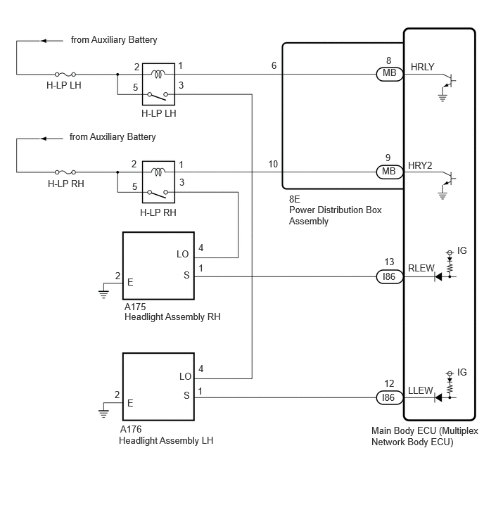
for GTMC Made
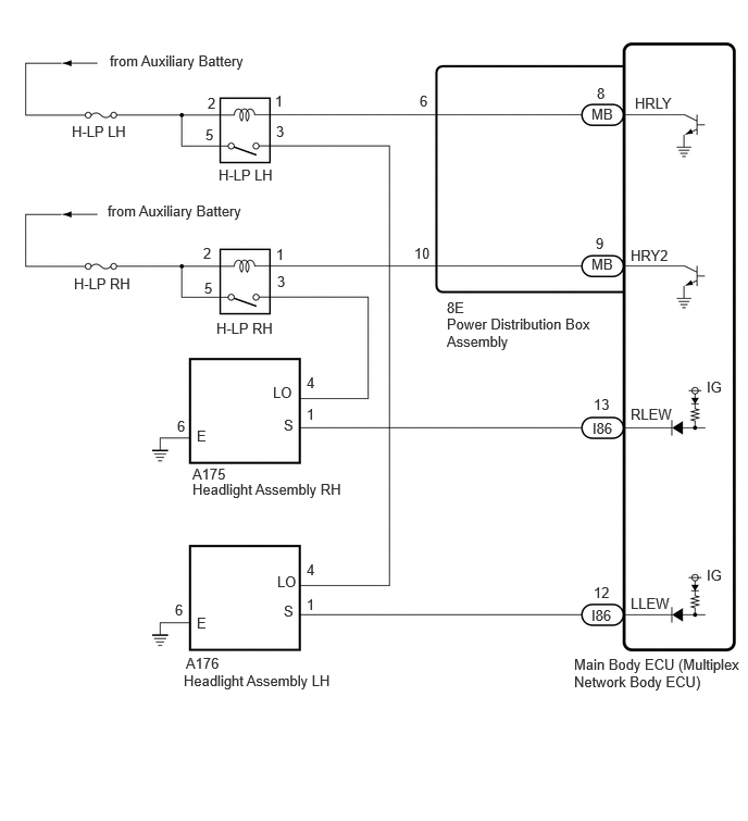
CAUTION / NOTICE / HINT
- NOTICE:
- ·
Inspect the fuses for circuits related to this system before performing the following procedure.
·Before replacing the main body ECU (multiplex network body ECU), refer to Service Bulletin.
PROCEDURE
- Body Electrical > Main Body > Clear DTCs
- 50002 449
- Result:
Proceed to NEXT
NEXT
Check for DTCs.
- Body Electrical > Main Body > Trouble Codes
- 50001 449
- OK:
DTC B243900 and B243A00 are not output.
- Result:
Result Proceed to DTCs are not output A B243949 is output B B243A49 is output C
A
B
C
Check vehicle type.
- Result:
Result Proceed to for TFTM Made A for GTMC Made B
A
B
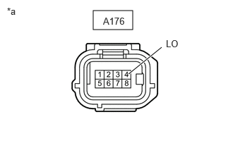
| *a | Front view of wire harness connector
(to Headlight Assembly LH) |
Disconnect the headlight assembly LH connector.
Measure the voltage according to the value(s) in the table below.
- Standard Voltage:
Tester Connection Switch Condition Specified Condition A176-4 (LO) - Body ground Light control switch in HEAD position 11 to 14 V
- Result:
Proceed to OK NG
OK
NG
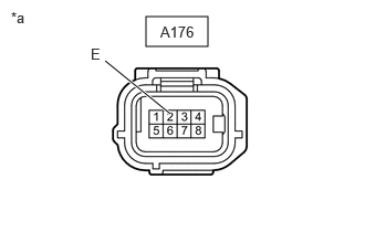
| *a | Front view of wire harness connector
(to Headlight Assembly LH) |
Measure the resistance according to the value(s) in the table below.
- Standard Resistance:
Tester Connection Condition Specified Condition A176-2 (E) - Body ground Always Below 1 Ω
- Result:
Proceed to OK NG
OK
NG
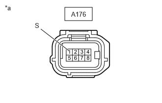
| *a | Front view of wire harness connector
(to Headlight Assembly LH) |
Measure the voltage according to the value(s) in the table below.
- Standard Voltage:
Tester Connection Switch Condition Specified Condition A176-1 (S) - Body ground Ignition switch ON 11 to 14 V
- Result:
Proceed to OK NG
OK
NG
Disconnect the I86 main body ECU (multiplex network body ECU) connector.
Measure the resistance according to the value(s) in the table below.
- Standard Resistance:
Tester Connection Condition Specified Condition A176-1 (S) - I86-12 (LLEW) Always Below 1 Ω A176-1 (S) - Body ground Always 10 kΩ or higher
- Result:
Proceed to OK NG
OK
NG
| *a | Front view of wire harness connector
(to Headlight Assembly LH) |
Disconnect the headlight assembly LH connector.
Measure the voltage according to the value(s) in the table below.
- Standard Voltage:
Tester Connection Switch Condition Specified Condition A176-4 (LO) - Body ground Light control switch in HEAD position 11 to 14 V
- Result:
Proceed to OK NG
OK
NG
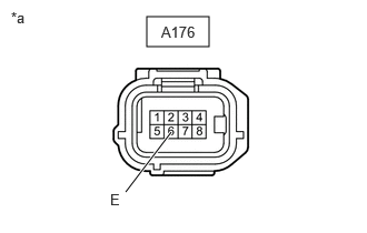
| *a | Front view of wire harness connector
(to Headlight Assembly LH) |
Measure the resistance according to the value(s) in the table below.
- Standard Resistance:
Tester Connection Condition Specified Condition A176-6 (E) - Body ground Always Below 1 Ω
- Result:
Proceed to OK NG
OK
NG
| *a | Front view of wire harness connector
(to Headlight Assembly LH) |
Measure the voltage according to the value(s) in the table below.
- Standard Voltage:
Tester Connection Switch Condition Specified Condition A176-1 (S) - Body ground Ignition switch ON 11 to 14 V
- Result:
Proceed to OK NG
OK
NG
Disconnect the I86 main body ECU (multiplex network body ECU) connector.
Measure the resistance according to the value(s) in the table below.
- Standard Resistance:
Tester Connection Condition Specified Condition A176-1 (S) - I86-12 (LLEW) Always Below 1 Ω A176-1 (S) - Body ground Always 10 kΩ or higher
- Result:
Proceed to OK NG
OK
NG
Remove the H-LP LH relay.
Measure the resistance according to the value(s) in the table below.
- Standard Resistance:
Tester Connection Condition Specified Condition 3 (H-LP LH relay) - A176-4 (LO) Always Below 1 Ω 3 (H-LP LH relay) - Body ground Always 10 kΩ or higher A176-4 (LO) - Body ground Always 10 kΩ or higher
- Result:
Proceed to OK NG
OK
NG
- Result:
Proceed to OK NG
OK
NG
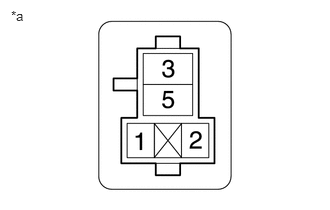
| *a | Front view of wire harness connector
(to H-LP LH Relay) |
Measure the voltage according to the value(s) in the table below.
- Standard Voltage:
Tester Connection Switch Condition Specified Condition 2 (H-LP LH relay) - Body ground Ignition switch off 11 to 14 V 5 (H-LP LH relay) - Body ground Ignition switch off 11 to 14 V
- Result:
Proceed to OK NG
OK
NG
Disconnect the 8E power distribution box assembly connector.
Measure the resistance according to the value(s) in the table below.
- Standard Resistance:
Tester Connection Condition Specified Condition 1 (H-LP LH relay) - 8E-6 Always Below 1 Ω 1 (H-LP LH relay) - Body ground Always 10 kΩ or higher 8E-6 - Body ground Always 10 kΩ or higher
- Result:
Proceed to OK NG
OK
NG
Remove the power distribution box assembly.
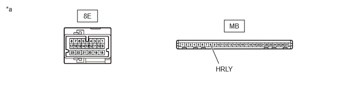
| *a | Component without harness connected
(Power Distribution Box Assembly) |
- | - |
Remove the main body ECU (multiplex network body ECU) from the power distribution box assembly.
Measure the resistance according to the value(s) in the table below.
- Standard Resistance:
Tester Connection Condition Specified Condition 8E-6 - MB-8 Always Below 1 Ω
- Result:
Proceed to OK NG
OK
NG
Check vehicle type.
- Result:
Result Proceed to for TFTM Made A for GTMC Made B
A
B
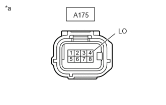
| *a | Front view of wire harness connector
(to Headlight Assembly RH) |
Disconnect the headlight assembly RH connector.
Measure the voltage according to the value(s) in the table below.
- Standard Voltage:
Tester Connection Switch Condition Specified Condition A175-4 (LO) - Body ground Light control switch in HEAD position 11 to 14 V
- Result:
Proceed to OK NG
OK
NG
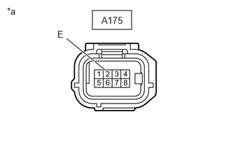
| *a | Front view of wire harness connector
(to Headlight Assembly RH) |
Measure the resistance according to the value(s) in the table below.
- Standard Resistance:
Tester Connection Condition Specified Condition A175-2 (E) - Body ground Always Below 1 Ω
- Result:
Proceed to OK NG
OK
NG
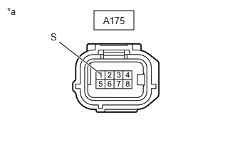
| *a | Front view of wire harness connector
(to Headlight Assembly RH) |
Measure the voltage according to the value(s) in the table below.
- Standard Voltage:
Tester Connection Switch Condition Specified Condition A175-1 (S) - Body ground Ignition switch ON 11 to 14 V
- Result:
Proceed to OK NG
OK
NG
Disconnect the I86 main body ECU (multiplex network body ECU) connector.
Measure the resistance according to the value(s) in the table below.
- Standard Resistance:
Tester Connection Condition Specified Condition A175-1 (S) - I86-13 (RLEW) Always Below 1 Ω A175-1 (S) - Body ground Always 10 kΩ or higher
- Result:
Proceed to OK NG
OK
NG
| *a | Front view of wire harness connector
(to Headlight Assembly RH) |
Disconnect the headlight assembly RH connector.
Measure the voltage according to the value(s) in the table below.
- Standard Voltage:
Tester Connection Switch Condition Specified Condition A175-4 (LO) - Body ground Light control switch in HEAD position 11 to 14 V
- Result:
Proceed to OK NG
OK
NG
| *a | Front view of wire harness connector
(to Headlight Assembly RH) |
Measure the resistance according to the value(s) in the table below.
- Standard Resistance:
Tester Connection Condition Specified Condition A175-6 (E) - Body ground Always Below 1 Ω
- Result:
Proceed to OK NG
OK
NG
| *a | Front view of wire harness connector
(to Headlight Assembly RH) |
Measure the voltage according to the value(s) in the table below.
- Standard Voltage:
Tester Connection Switch Condition Specified Condition A175-1 (S) - Body ground Ignition switch ON 11 to 14 V
- Result:
Proceed to OK NG
OK
NG
Disconnect the I86 main body ECU (multiplex network body ECU) connector.
Measure the resistance according to the value(s) in the table below.
- Standard Resistance:
Tester Connection Condition Specified Condition A175-1 (S) - I86-13 (RLEW) Always Below 1 Ω A175-1 (S) - Body ground Always 10 kΩ or higher
- Result:
Proceed to OK NG
OK
NG
Remove the H-LP RH relay.
Measure the resistance according to the value(s) in the table below.
- Standard Resistance:
Tester Connection Condition Specified Condition 3 (H-LP RH relay) - A175-4 (LO) Always Below 1 Ω 3 (H-LP RH relay) - Body ground Always 10 kΩ or higher A175-4 (LO) - Body ground Always 10 kΩ or higher
- Result:
Proceed to OK NG
OK
NG
- Result:
Proceed to OK NG
OK
NG
| *a | Front view of wire harness connector
(to H-LP RH Relay) |
Measure the voltage according to the value(s) in the table below.
- Standard Voltage:
Tester Connection Switch Condition Specified Condition 2 (H-LP RH relay) - Body ground Ignition switch off 11 to 14 V 5 (H-LP RH relay) - Body ground Ignition switch off 11 to 14 V
- Result:
Proceed to OK NG
OK
NG
Disconnect the 8E power distribution box assembly connector.
Measure the resistance according to the value(s) in the table below.
- Standard Resistance:
Tester Connection Condition Specified Condition 1 (H-LP RH relay) - 8E-10 Always Below 1 Ω 1 (H-LP RH relay) - Body ground Always 10 kΩ or higher 8E-10 - Body ground Always 10 kΩ or higher
- Result:
Proceed to OK NG
OK
NG
Remove the power distribution box assembly.
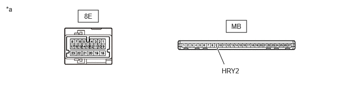
| *a | Component without harness connected
(Power Distribution Box Assembly) |
- | - |
Remove the main body ECU (multiplex network body ECU) from the power distribution box assembly.
Measure the resistance according to the value(s) in the table below.
- Standard Resistance:
Tester Connection Condition Specified Condition 8E-10 - MB-9 (HRY2) Always Below 1 Ω
- Result:
Proceed to OK NG
OK
NG