AUDIO / VIDEO RADIO ANTENNA CORD INSTALLATION
CAUTION / NOTICE / HINT
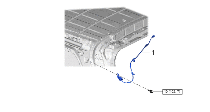
| Procedure | Part Name Code | 
|

|

|
|
|---|---|---|---|---|---|
| 1 | NO. 3 ANTENNA CORD SUB-ASSEMBLY | 86101D | - | - | - |

|
N*m (kgf*cm, ft.*lbf): Specified torque | - | - |
| Procedure | Part Name Code |
|
|
|
|
|---|---|---|---|---|---|
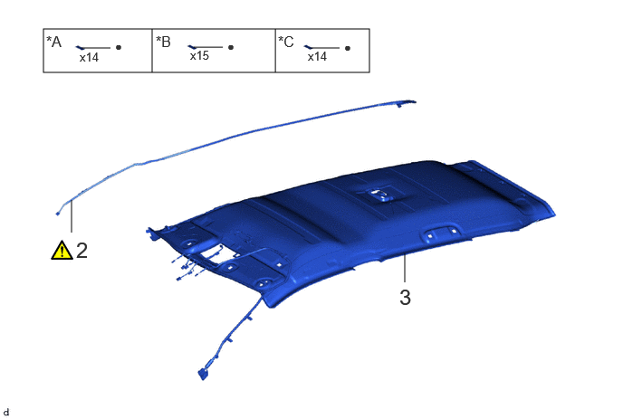
| 2 | NO. 2 ANTENNA CORD SUB-ASSEMBLY | 86101J | ( 202201,999999,_56,_111966,_0499967,RM100000001Z100_01_0228,) 202201,999999,_56,_111966,_0499967,RM100000001Z100_01_0228,)
|
- | - |
| 3 | ROOF HEADLINING ASSEMBLY | 63310 | - | - | - |
| *A | for Normal Roof | *B | for Moon Roof |
| *C | for Panoramic Moon Roof | - | - |
| ● | Non-reusable part | - | - |
| Procedure | Part Name Code |
|
|
|
|
|---|---|---|---|---|---|
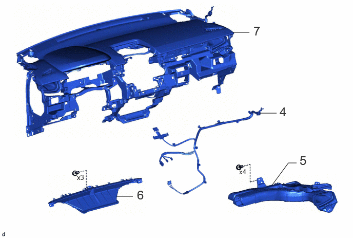
| 4 | ANTENNA CORD SUB-ASSEMBLY | 86101 | - | - | - |
| 5 | NO. 2 HEATER TO REGISTER DUCT SUB-ASSEMBLY | 55085 | - | - | - |
| 6 | DEFROSTER NOZZLE ASSEMBLY | 55950G | - | - | - |
| 7 | INSTRUMENT PANEL SAFETY PAD ASSEMBLY | - | - | - | - |
PROCEDURE

 86101D
1.INSTALL NO. 3 ANTENNA CORD SUB-ASSEMBLY
86101D
1.INSTALL NO. 3 ANTENNA CORD SUB-ASSEMBLY
- Torque:
- 10 N*m (102 kgf*cm, 7 ft.*lbf)
86101J
2.INSTALL NO. 2 ANTENNA CORD SUB-ASSEMBLY
for Normal Roof:
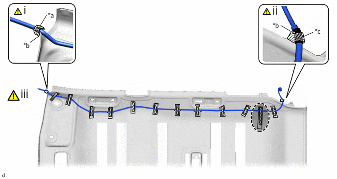
| *a | Marking Tape (A) | *b | Protrusion |
| *c | Marking Tape (B) | - | - |

|
Adhesive Tape | 
|
Adjustment Area |
Align the marking tape (A) on the No. 2 antenna cord sub-assembly with the protrusion on the front of the roof headlining assembly and wrap adhesive tape around the No. 2 antenna cord sub-assembly and protrusion of the roof headlining assembly.
Align the marking tape (B) on the No. 2 antenna cord sub-assembly with the protrusion on the rear of the roof headlining assembly and wrap adhesive tape around the No. 2 antenna cord sub-assembly and protrusion of the roof headlining assembly.
Install the No. 2 antenna cord sub-assembly with 12 new adhesive tapes.
- NOTICE:
- ·
Apply the adhesive tape securely in place.
·Do not touch the adhesive surface when applying the adhesive tape to prevent adhesion failure.
·Secure the extra length of the No. 2 antenna cord sub-assembly in the adjustment area.
for Moon Roof:
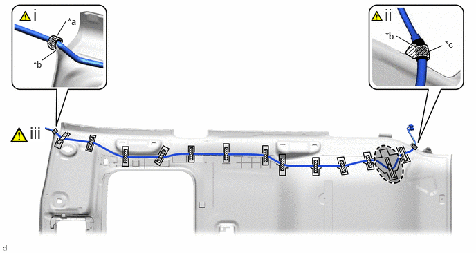
| *a | Marking Tape (A) | *b | Protrusion |
| *c | Marking Tape (B) | - | - |
|
|
Adhesive Tape |
|
Adjustment Area |
Align the marking tape (A) on the No. 2 antenna cord sub-assembly with the protrusion on the front of the roof headlining assembly and wrap adhesive tape around the No. 2 antenna cord sub-assembly and protrusion of the roof headlining assembly.
Align the marking tape (B) on the No. 2 antenna cord sub-assembly with the protrusion on the rear of the roof headlining assembly and wrap adhesive tape around the No. 2 antenna cord sub-assembly and protrusion of the roof headlining assembly.
Install the No. 2 antenna cord sub-assembly with 13 new adhesive tapes.
- NOTICE:
- ·
Apply the adhesive tape securely in place.
·Do not touch the adhesive surface when applying the adhesive tape to prevent adhesion failure.
·Secure the extra length of the No. 2 antenna cord sub-assembly in the adjustment area.
for Panoramic Moon Roof:

| *a | Marking Tape (A) | *b | Protrusion |
| *c | Marking Tape (B) | - | - |
|
|
Adhesive Tape |
|
Adjustment Area |
Align the marking tape (A) on the No. 2 antenna cord sub-assembly with the protrusion on the front of the roof headlining assembly and wrap adhesive tape around the No. 2 antenna cord sub-assembly and protrusion of the roof headlining assembly.
Align the marking tape (B) on the No. 2 antenna cord sub-assembly with the protrusion on the rear of the roof headlining assembly and wrap adhesive tape around the No. 2 antenna cord sub-assembly and protrusion of the roof headlining assembly.
Install the No. 2 antenna cord sub-assembly with 12 new adhesive tapes.
- NOTICE:
- ·
Apply the adhesive tape securely in place.
·Do not touch the adhesive surface when applying the adhesive tape to prevent adhesion failure.
·Secure the extra length of the No. 2 antenna cord sub-assembly in the adjustment area.
63310
3.INSTALL ROOF HEADLINING ASSEMBLY
86101
4.INSTALL ANTENNA CORD SUB-ASSEMBLY
55085
5.INSTALL NO. 2 HEATER TO REGISTER DUCT SUB-ASSEMBLY
55950G
6.INSTALL DEFROSTER NOZZLE ASSEMBLY
7.INSTALL INSTRUMENT PANEL SAFETY PAD ASSEMBLY