DOOR / HATCH POWER BACK DOOR SYSTEM Back Door Closer does not Operate
DESCRIPTION
The back door lock with courtesy light switch assembly is controlled by the multiplex network door ECU. The multiplex network door ECU is activated according to the switch signals in the back door lock with courtesy light switch assembly.
WIRING DIAGRAM
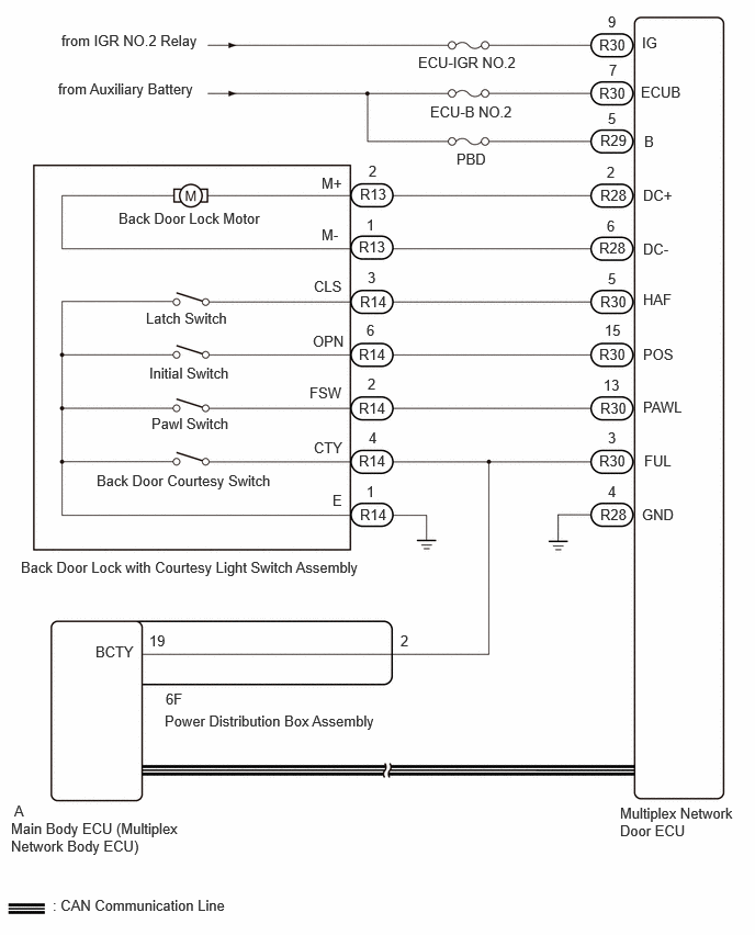
CAUTION / NOTICE / HINT
- NOTICE:
- ·
First perform the communication function inspections in How to Proceed with Troubleshooting to confirm that there are no CAN communication malfunctions before troubleshooting this problem.
·Inspect fuses for circuits related to this system before performing the following inspection procedure.
·If the multiplex network door ECU has been replaced, or if any of the connectors has been disconnected, initialize the power back door system.
PROCEDURE
Check for DTCs.
- Body Electrical > Back Door > Trouble Codes
- 50001 489
- Result:
Result Proceed to DTC is not output A DTC B225001 is output B DTC B225101 is output C
A
B
C
Check if the back door can be fully closed by hand.
- Result:
Result Proceed to The back door can be closed normally A The back door cannot be closed normally B
A
B
Disconnect the R28, R29 and R30 multiplex network door ECU connectors.
Measure the resistance according to the value(s) in the table below.
- Standard Resistance:
Tester Connection Condition Specified Condition R28-4 (GND) - Body ground Always Below 1 Ω
Measure the voltage according to the value(s) in the table below.
- Standard Voltage:
Tester Connection Switch Condition Specified Condition R30-7 (ECUB) - Body ground Ignition switch off 11 to 14 V R29-5 (B) - Body ground Ignition switch off 11 to 14 V R30-9 (IG) - Body ground Ignition switch ON 11 to 14 V Ignition switch off Below 1 V
- Result:
Proceed to OK NG
OK
NG
- Result:
Proceed to OK NG
OK
NG
Click hereVehicle Interior>DOOR LOCK>BACK DOOR LOCK>REMOVAL201910,999999,_58,_083092,_0403682,RM100000001JUF3,
Disconnect the R13 and R14 back door lock with courtesy light switch connectors.
Disconnect the R28 and R30 multiplex network door ECU connectors.
Disconnect the 6F power distribution box assembly connector.
Measure the resistance according to the value(s) in the table below.
- Standard Resistance:
Tester Connection Condition Specified Condition R13-2 (M+) - R28-2 (DC+) Always Below 1 Ω R13-1 (M-) - R28-6 (DC-) Always Below 1 Ω R14-4 (CTY) - R30-3 (FUL) Always Below 1 Ω R14-2 (FSW) - R30-13 (PAWL) Always Below 1 Ω R14-3 (CLS) - R30-5 (HAF) Always Below 1 Ω R14-6 (OPN) - R30-15 (POS) Always Below 1 Ω R14-1 (E) - Body ground Always Below 1 Ω R13-2 (M+) or R28-2 (DC+) - Body ground Always 10 kΩ or higher R13-1 (M-) or R28-6 (DC-) - Body ground Always 10 kΩ or higher R14-4 (CTY) or R30-3 (FUL) - Body ground Always 10 kΩ or higher R14-2 (FSW) or R30-13 (PAWL) - Body ground Always 10 kΩ or higher R14-3 (CLS) or R30-5 (HAF) - Body ground Always 10 kΩ or higher R14-6 (OPN) or R30-15 (POS) - Body ground Always 10 kΩ or higher
- Result:
Proceed to OK NG
OK
NG