DOOR / HATCH FUEL LID OPENER SYSTEM Fuel Lid Opener does not Operate
DESCRIPTION
When the fuel lid opener switch is pushed, a fuel lid opener switch signal is sent to the ECM. The ECM turns on the FUEL OPN relay and the fuel lid with motor lock assembly opens the fuel lid. When the fuel lid is open, a fuel lid courtesy switch signal is output from the fuel lid with motor lock assembly.
WIRING DIAGRAM
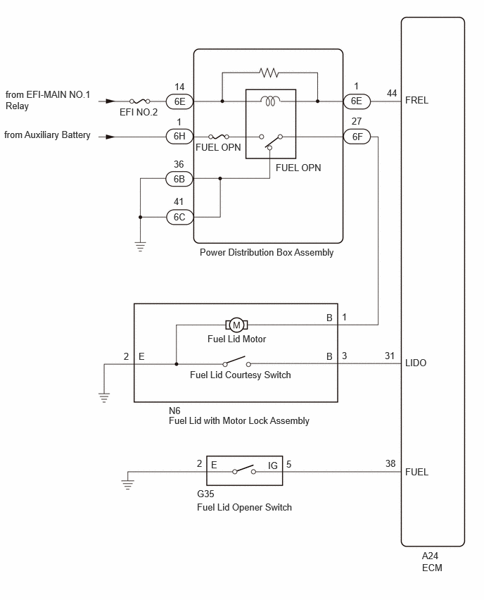
CAUTION / NOTICE / HINT
- NOTICE:
- ·
Inspect the fuses for circuits related to this system before performing the following procedure.
·Perform Registration (VIN registration) after replacing the ECM.
PROCEDURE
Perform the Active Test according to the display on the GTS.
- Powertrain > Engine > Active Test
-
Tester Display Measurement Item Control Range Diagnostic Note Activate the Fuel Filler Opener Activate fuel lid with motor lock assembly (fuel lid motor) OFF or ON -
- Powertrain > Engine > Active Test
-
Tester Display Activate the Fuel Filler Opener - 50004 372 41
- OK:
The fuel lid with motor lock assembly operates normally.
- Result:
Proceed to OK NG
OK
NG
Read the Data List according to the display on the GTS.
- Powertrain > Engine > Data List
-
Tester Display Measurement Item Range Normal Condition Diagnostic Note Fuel Lid SW Fuel lid opener switch status Close or Open Close: Fuel lid opener switch not pushed
Open: Fuel lid opener switch pushed-
- Powertrain > Engine > Data List
-
Tester Display Fuel Lid SW - 50003 372 37
- OK:
The GTS display changes correctly in response to the operation of the fuel lid opener switch.
- Result:
Proceed to OK NG
OK
NG
Read the Data List according to the display on the GTS.
- Powertrain > Engine > Data List
-
Tester Display Measurement Item Range Normal Condition Diagnostic Note Fuel Lid Sensor SW Fuel lid with motor lock assembly (fuel lid courtesy switch) status Close or Open Close: Fuel lid closed
Open: Fuel lid open-
- Powertrain > Engine > Data List
-
Tester Display Fuel Lid Sensor SW - 50003 372 38
- OK:
The GTS display changes correctly in response to the operation of the fuel lid open and closed.
- Result:
Proceed to OK NG
OK
for A25B-FXS:
for A25D-FXS:
for A25F-FXS (Production date from 2021/08):
NG
Remove the fuel lid with motor lock assembly (fuel lid courtesy switch).
Inspect the fuel lid with motor lock assembly (fuel lid courtesy switch).
- Result:
Proceed to OK NG
OK
NG
Disconnect the N6 fuel lid with motor lock assembly connector.
Disconnect the A24 ECM connector.
Measure the resistance according to the value(s) in the table below.
- Standard Resistance:
Tester Connection Condition Specified Condition N6-3 (B) - A24-31 (LIDO) Always Below 1 Ω N6-3 (B) or A24-31 (LIDO) - Body ground Always 10 kΩ or higher
- Result:
Proceed to OK NG
OK
for A25B-FXS:
for A25D-FXS:
for A25F-FXS (Production date from 2021/08):
NG
Remove the fuel lid opener switch.
Inspect the fuel lid opener switch.
- Result:
Proceed to OK NG
OK
NG
Disconnect the G35 fuel lid opener switch connector.
Disconnect the A24 ECM connector.
Measure the resistance according to the value(s) in the table below.
- Standard Resistance:
Tester Connection Condition Specified Condition G35-5 (IG) - A24-38 (FUEL) Always Below 1 Ω G35-2 (E) - Body ground Always Below 1 Ω G35-5 (IG) or A24-38 (FUEL) - Body ground Always 10 kΩ or higher
- Result:
Proceed to OK NG
OK
for A25B-FXS:
for A25D-FXS:
for A25F-FXS (Production date from 2021/08):
NG
Remove the fuel lid with motor lock assembly (fuel lid motor).
Inspect the fuel lid with motor lock assembly (fuel lid motor).
- Result:
Proceed to OK NG
OK
NG
Disconnect the power distribution box assembly connectors.
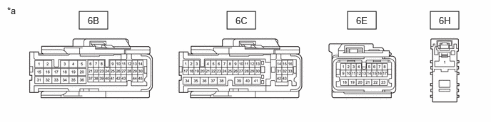
| *a | Front view of wire harness connector
(to Power Distribution Box Assembly) |
- | - |
Measure the voltage according to the value(s) in the table below.
- Standard Voltage:
Tester Connection Switch Condition Specified Condition 6H-1 - Body ground Power switch off 11 to 14 V 6E-14 - Body ground Power switch on (IG) 11 to 14 V Power switch off Below 1 V
Measure the resistance according to the value(s) in the table below.
- Standard Resistance:
Tester Connection Condition Specified Condition 6B-36 - Body ground Always Below 1 Ω 6C-41 - Body ground Always Below 1 Ω
- Result:
Proceed to OK NG
OK
NG
Disconnect the 6E power distribution box assembly connector.
Disconnect the A24 ECM connector.
Measure the resistance according to the value(s) in the table below.
- Standard Resistance:
Tester Connection Condition Specified Condition 6E-1 - A24-44 (FREL) Always Below 1 Ω 6E-1 or A24-44 (FREL) - Body ground Always 10 kΩ or higher
- Result:
Proceed to OK NG
OK
NG
Disconnect the N6 fuel lid with motor lock assembly connector.
Disconnect the 6F power distribution box assembly connector.
Measure the resistance according to the value(s) in the table below.
- Standard Resistance:
Tester Connection Condition Specified Condition N6-1 (B) - 6F-27 Always Below 1 Ω N6-2 (E) - Body ground Always Below 1 Ω N6-1 (B) or 6F-27 - Body ground Always 10 kΩ or higher
- Result:
Proceed to OK NG
OK
NG
Remove the power distribution box assembly.
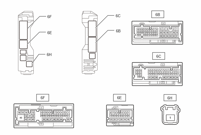
Measure the resistance according to the value(s) in the table below.
- Standard Resistance:
Tester Connection Condition Specified Condition 6H-1 - 6F-27 Auxiliary battery voltage applied between terminals 6E-1 and 6E-14 Below 1 Ω 6H-1 - 6F-27 Auxiliary battery voltage not applied between terminals 6E-1 and 6E-14 10 kΩ or higher 6B-36 - 6F-27 Auxiliary battery voltage not applied between terminals 6E-1 and 6E-14 Below 1 Ω 6C-41 - 6F-27 Auxiliary battery voltage not applied between terminals 6E-1 and 6E-14 Below 1 Ω 6B-36 - 6F-27 Auxiliary battery voltage applied between terminals 6E-1 and 6E-14 10 kΩ or higher 6C-41 - 6F-27 Auxiliary battery voltage applied between terminals 6E-1 and 6E-14 10 kΩ or higher
- Result:
Proceed to OK NG
OK
for A25B-FXS:
for A25D-FXS:
for A25F-FXS (Production date from 2021/08):
NG