RM36D0EC _58 Vehicle Interior _083094 THEFT DETERRENT / KEYLESS ENTRY _0712331 THEFT DETERRENT SYSTEM J

THEFT DETERRENT / KEYLESS ENTRY  THEFT DETERRENT SYSTEM  Horn Circuit  


DESCRIPTION

When the theft deterrent system is switched from the armed state to the alarm sounding state, the main body ECU (multiplex network body ECU) transmits a signal to cause the horn to sound at intervals of 0.4 seconds.

WIRING DIAGRAM
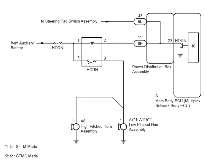
B637438E48
0.375,1.427 1.24,2.094 0.865,0.667 10 false from Auxiliary Battery 3.042,2.365 3.656,2.563 0.615,0.198 10 false HORN 1.823,1.594 2.438,1.792 0.615,0.198 10 false HORN 6.146,1.344 6.76,1.542 0.615,0.198 10 false HORN 4.531,4.292 5.635,4.677 1.104,0.385 10 false Low Pitched Horn Assembly 4.646,2.26 6.073,2.792 1.427,0.531 10 false Power Distribution Box Assembly 5.458,3.458 7.135,3.99 1.677,0.531 10 false Main Body ECU (Multiplex Network Body ECU) 2.708,1.344 2.927,1.542 0.219,0.198 10 false 1 3.646,1.333 3.865,1.531 0.219,0.198 10 false 2 4.208,4.146 4.427,4.344 0.219,0.198 10 false 1 4.531,4.115 5.573,4.365 1.042,0.25 10 false A7*1, A115*2 5.906,1.344 6.26,1.542 0.354,0.198 10 false 23 5.458,3.281 5.813,3.479 0.354,0.198 10 false A 6.74,1.531 7.094,1.729 0.354,0.198 10 false IC 4.844,1.229 5.198,1.427 0.354,0.198 10 false 11 3.646,1.958 3.865,2.156 0.219,0.198 10 false 3 2.719,1.948 2.938,2.146 0.219,0.198 10 false 5 2.833,4.354 3.979,4.75 1.146,0.396 10 false High Pitched Horn Assembly 2.833,4.167 3.271,4.385 0.438,0.219 10 false A8 2.521,4.156 2.74,4.354 0.219,0.198 10 false 1 1.438,0.656 4.25,0.885 2.813,0.229 10 false to Steering Pad Switch Assembly 4.854,0.469 5.167,0.667 0.313,0.198 10 false 43 4.844,0.667 5.156,0.865 0.313,0.198 10 false 6B 4.844,1.448 5.156,1.646 0.313,0.198 10 false 6E 0.156,5.063 1.677,5.344 1.521,0.281 10 false *1: for SFTM Made 0.156,5.396 1.677,5.677 1.521,0.281 10 false *2: for GTMC Made

CAUTION / NOTICE / HINT

NOTICE:
·

Inspect the fuses for circuits related to this system before performing the following procedure.

·

If the main body ECU (multiplex network body ECU) is replaced, refer to the Service Bulletin.


PROCEDURE

1.CHECK HORNS OPERATION
a.

Press the horn switch and check if the horns sound.


Result:
Proceed to
Horns sound
Horns do not sound


Horns sound

2.CHECK HARNESS AND CONNECTOR (HORN RELAY ASSEMBLY [HORN] - POWER DISTRIBUTION BOX ASSEMBLY)

Horns do not sound

2.CHECK HARNESS AND CONNECTOR (HORN RELAY ASSEMBLY [HORN] - POWER DISTRIBUTION BOX ASSEMBLY)
a.

Disconnect the 6E power distribution box assembly connector.


b.

Remove the horn relay assembly (HORN).


c.

Measure the resistance according to the value(s) in the table below.

Standard Resistance:
Tester Connection Condition Specified Condition
Horn relay assembly (HORN) terminal 2 - 6E-11 Always Below 1 Ω


Result:
Proceed to
OK
NG


OK

3.INSPECT POWER DISTRIBUTION BOX ASSEMBLY

NG

REPAIR OR REPLACE HARNESS OR CONNECTOR

3.INSPECT POWER DISTRIBUTION BOX ASSEMBLY

b.
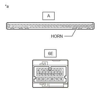
E439027C28
1.438,0.406 1.833,0.667 0.396,0.26 1.5,1.667 1.896,1.927 0.396,0.26 2.427,1.219 2.604,0.896 true 2.167,1.219 2.427,1.219 false 0.167,0.125 0.479,0.323 0.313,0.198 10 false *a 1.594,0.448 1.75,0.646 0.156,0.198 10 false A 1.625,1.719 2.063,1.917 0.438,0.198 10 false 6E 1.719,1.135 2.333,1.333 0.615,0.198 10 false HORN
*a Component without harness connected(Power Distribution Box Assembly)


Measure the resistance according to the value(s) in the table below.

Standard Resistance:
Tester Connection Condition Specified Condition
6E-11 - A-23 (HORN) Always Below 1 Ω


Result:
Proceed to
OK
NG


OK

NG