LIGHTING (INT) LIGHTING SYSTEM Push Start Switch Illumination Circuit
DESCRIPTION
The illuminated entry system controls the push start switch illumination.
WIRING DIAGRAM
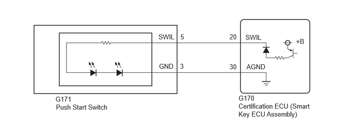
CAUTION / NOTICE / HINT
- NOTICE:
- ·
Check that the "Start Indicator Function" customization setting is set to "ON".
·Before replacing the certification ECU (smart key ECU assembly), refer to Service Bulletin.
PROCEDURE
Perform the Active Test according to the display on the GTS.
- Body Electrical > Entry&Start > Active Test
-
Tester Display Measurement Item Control Range Diagnostic Note Start SW Light Power Supply Push start switch illumination OFF or ON -
- Body Electrical > Entry&Start > Active Test
-
Tester Display Start SW Light Power Supply - 50004 440 1
- OK:
Push start switch illumination comes on.
- Result:
Proceed to OK NG
OK
NG
Remove the push start switch.
Inspect the push start switch.
- Result:
Proceed to OK NG
OK
NG
for M20C-FKS: Click hereEngine / Hybrid System>M20C-FKS (STARTING)>ENGINE SWITCH>REMOVAL202004,999999,_51,_087043,_0418185,RM100000001MIWG,
for A25B-FXS: Click hereEngine / Hybrid System>A25B-FXS (STARTING)>POWER SWITCH>REMOVAL201910,999999,_51,_083054,_0402944,RM100000001JLYS,
for A25D-FXS: Click hereEngine / Hybrid System>A25D-FXS (STARTING)>POWER SWITCH>REMOVAL202104,999999,_51,_104053,_0478450,RM100000001WKBM,
for M20D-FKS: Click hereEngine / Hybrid System>M20D-FKS (STARTING)>ENGINE SWITCH>REMOVAL201910,999999,_51,_083065,_0402941,RM100000001JLYH,
for A25F-FXS: Click hereEngine / Hybrid System>A25F-FXS (STARTING)>POWER SWITCH (Production date from 2021/08)>REMOVAL201910,999999,_51,_105216,_0486274,RM100000001XHFI,
Disconnect the G171 push start switch connector.
Disconnect the G170 certification ECU (smart key ECU assembly) connector.
Measure the resistance according to the value(s) in the table below.
- Standard Resistance:
Tester Connection Condition Specified Condition G171-5 (SWIL) - G170-20 (SWIL) Always Below 1 Ω G171-3 (GND) - G170-30 (AGND) Always Below 1 Ω G171-5 (SWIL) or G170-20 (SWIL) - Body ground Always 10 kΩ or higher G171-3 (GND) or G170-30 (AGND) - Body ground Always 10 kΩ or higher
- Result:
Proceed to OK NG
OK
NG