LIGHTING (INT) LIGHTING SYSTEM IG Signal Circuit
DESCRIPTION
This circuit detects the ignition switch ON or off condition, and sends it to the main body ECU (multiplex network body ECU).
WIRING DIAGRAM
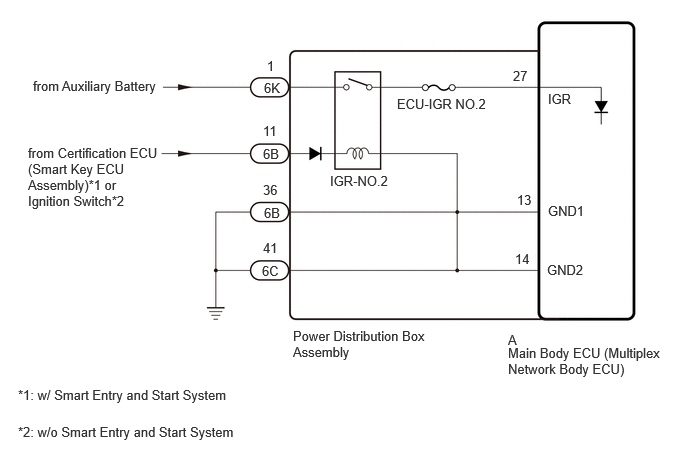
CAUTION / NOTICE / HINT
- NOTICE:
- ·
Inspect the fuses for circuits related to this system before performing the following procedure.
·w/ Smart Entry and Start System:
Before replacing the main body ECU (multiplex network body ECU), refer to Service Bulletin.
PROCEDURE
Check vehicle type.
- Result:
Result Proceed to w/ Smart Entry and Start System A w/o Smart Entry and Start System B
A
B
Check for DTCs.
- Body Electrical > Power Source Control > Trouble Codes
- 50001 454
- OK:
Smart entry and start system (for Start Function) DTCs are not output.
- Result:
Proceed to OK NG
OK
NG
for HV Model: Click hereVehicle Interior>THEFT DETERRENT / KEYLESS ENTRY>SMART ENTRY AND START SYSTEM (for Start Function, HV Model)>HOW TO PROCEED WITH TROUBLESHOOTING202409,999999,_58,_083094,_0402999,RM100000002NSRK,
for Gasoline Model: Click hereVehicle Interior>THEFT DETERRENT / KEYLESS ENTRY>SMART ENTRY AND START SYSTEM (for Start Function, Gasoline Model)>HOW TO PROCEED WITH TROUBLESHOOTING202409,999999,_58,_083094,_0403000,RM100000002NSSW,
Read the Data List according to the display on the GTS.
- Body Electrical > Main Body > Data List
-
Tester Display Measurement Item Range Normal Condition Diagnostic Note IGR Power Ignition switch ON signal OFF or ON OFF: Ignition switch off
ON: Ignition switch ON-
- Body Electrical > Main Body > Data List
-
Tester Display IGR Power - 50003 449 122
- OK:
Normal conditions listed above are displayed.
- Result:
Proceed to OK NG
OK
NG
Disconnect the power distribution box assembly connectors.
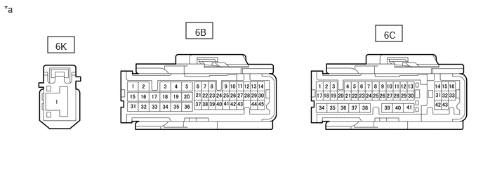
| *a | Front view of wire harness connector
(to Power Distribution Box Assembly) |
- | - |
Measure the voltage according to the value(s) in the table below.
- Standard Voltage:
Tester Connection Switch Condition Specified Condition 6K-1 - Body ground Ignition switch off 11 to 14 V 6B-11 - Body ground Ignition switch ON 11 to 14 V Ignition switch off Below 1 V
Measure the resistance according to the value(s) in the table below.
- Standard Resistance:
Tester Connection Condition Specified Condition 6B-36 - Body ground Always Below 1 Ω 6C-41 - Body ground Always Below 1 Ω
- Result:
Proceed to OK NG
OK
NG
Remove the power distribution box assembly.
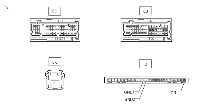
| *a | Component without harness connected
(Power Distribution Box Assembly) |
- | - |
Remove the main body ECU (multiplex network body ECU) from the power distribution box assembly.
Measure the resistance according to the value(s) in the table below.
- Standard Resistance:
Tester Connection Condition Specified Condition A-27 (IGR) - 6K-1 Auxiliary battery not connected to 6B-11 and 6B-36 10 kΩ or higher Auxiliary battery positive (+) → 6B-11
Auxiliary battery negative (-) → 6B-36Below 1 Ω A-13 (GND1) - 6B-36 Always Below 1 Ω A-16 (GND2) - 6C-41 Always Below 1 Ω
- Result:
Proceed to OK NG
OK
NG