DOOR LOCK WIRELESS DOOR LOCK CONTROL SYSTEM(w/ Smart Entry and Start System) B124296 Wireless Door Lock Tuner Component Internal Failure
DESCRIPTION
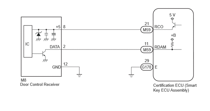
The door control receiver receives a signal from the electrical key transmitter sub-assembly and sends signals to the main body ECU (multiplex network body ECU) through the certification ECU (smart key ECU assembly) via CAN communication system. The certification ECU (smart key ECU assembly) sends door lock/unlock commands to the main body ECU (multiplex network body ECU).
| DTC No. | Detection Item | DTC Detection Condition | Trouble Area |
|---|---|---|---|
| B124296 | Wireless Door Lock Tuner Component Internal Failure | One of the following conditions is met:
·
Short in RDAM between the certification ECU (smart key ECU assembly) and door control receiver. ·
Short in RCO between the certification ECU (smart key ECU assembly) and door control receiver. |
·
Door control receiver ·
Certification ECU (smart key ECU assembly) ·
Harness or connector |
WIRING DIAGRAM
CAUTION / NOTICE / HINT
- NOTICE:
- ·
When using the GTS with the ignition switch off, connect the GTS to the DLC3 and turn a courtesy light switch on and off at intervals of 1.5 seconds or less until communication between the GTS and the vehicle begins. Then select the vehicle type under manual mode and enter the following menus: Body Electrical / Entry & Start. While using the GTS, periodically turn a courtesy light switch on and off at intervals of 1.5 seconds or less to maintain communication between the GTS and the vehicle.
·If the certification ECU (smart key ECU assembly) is replaced, refer to Service Bulletin.
·When replacing or inspecting the door control receiver and wire harness, do not change the position or length of the wire harness. If the wire harness is too close to the door control receiver, entry and start function and wireless control function performance may be affected.
·Check that there are no electrical key transmitter sub-assemblies in the vehicle.
·This DTC is not stored within 10 seconds of the ignition switch being turned from ON to off.
·When replacing the door control receiver, read the transmitter IDs (tire pressure warning system) stored in the old ECU using the GTS and write them down before removal.
·It is necessary to perform initialization after registration of the transmitter IDs into the door control receiver if the door control receiver has been replaced.
-
PROCEDURE
Disconnect the M8 door control receiver connector.
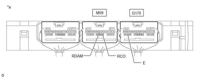
| *a | Component with harness connected
(Certification ECU (Smart Key ECU Assembly)) |
- | - |
Measure the voltage and resistance and check for pulses according to the value(s) in the table below.
- Standard Voltage:
Tester Connection Condition Specified Condition M59-11 (RDAM) - G170-29 (E) Always 11 to 14 V M59-21 (RCO) - G170-29 (E) Always Pulse generation at regular intervals
(Below 1 V ←→ 4.5 to 5.5 V)
- Standard Resistance:
Tester Connection Condition Specified Condition G170-29 (E) - Body ground Always Below 1 Ω
- Result:
Proceed to OK NG
OK
NG
Disconnect the M59 certification ECU (smart key ECU assembly) connector.
Disconnect the M8 door control receiver connector.
Measure the resistance according to the value(s) in the table below.
- Standard Resistance:
Tester Connection Condition Specified Condition M59-11 (RDAM) - M8-2 (DATA) Always Below 1 Ω M59-21 (RCO) - M8-8 (+5) Always Below 1 Ω M8-12 (GND) - Body ground Always Below 1 Ω M8-2 (DATA) or M59-11 (RDAM) - Other terminals and body ground Always 10 kΩ or higher M8-8 (+5) or M59-21 (RCO) - Other terminals and body ground Always 10 kΩ or higher
- Result:
Proceed to OK NG
OK
NG