WINDOW / GLASS WINDOW DEFOGGER SYSTEM Rear Window Defogger System does not Operate
DESCRIPTION
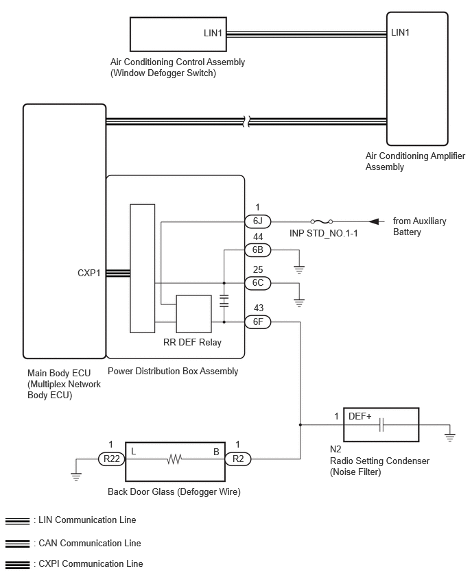
An operation request signal is sent to the air conditioning amplifier assembly via LIN communication when the window defogger switch (air conditioning control assembly) is operated. When the air conditioning amplifier assembly receives the signal, it sends an operation request signal via CAN communication to the main body ECU (multiplex network body ECU). When the main body ECU (multiplex network body ECU) receives the signal, it sends an operation request signal via CPXI communication to the power distribution box assembly. After the operation request signal is received by the power distribution box assembly, it outputs an operation signal and operates the window defogger.
WIRING DIAGRAM
CAUTION / NOTICE / HINT
- NOTICE:
- ·
If the window defogger system is operated when the auxiliary battery voltage is low, due to the electrical load limit control that gives voltage supply priority to the power steering system, the window defogger system may not operate. In this case, check the vehicle control history of the power steering system and check that "Battery Voltage Drop: X208F" is not stored before proceeding with troubleshooting.
·With the negative (-) auxiliary battery terminal connected, disconnect/do not connect the connector of the power distribution box assembly.
·When replacing the power distribution box assembly, the system may not operate normally if the same part number is not used.
·The window defogger system uses the CAN communication system, LIN communication system and CXPI communication system. Inspect the communication function by following How to Proceed with Troubleshooting.
- HINT:
-
Inspect the fuses for circuits related to this system before performing the following procedure.
PROCEDURE
Read the Data List according to the display on the GTS.
- Body Electrical > Power Distribution Box > Data List
-
Tester Display Measurement Item Range Normal Condition Diagnostic Note Rear Defogger Input Signal Window defogger switch signal input condition OFF/ON OFF: Window defogger switch off
ON: Window defogger switch on-
- Body Electrical > Power Distribution Box > Data List
-
Tester Display Rear Defogger Input Signal - 50003 475 1280
- OK:
On the GTS screen, ON or OFF is displayed accordingly.
- Result:
Proceed to OK NG
OK
NG
Read the Data List according to the display on the GTS.
- Body Electrical > Power Distribution Box > Data List
-
Tester Display Measurement Item Range Normal Condition Diagnostic Note Rear Defogger Output Signal Window defogger output condition OFF/ON OFF: Window defogger does not operate
ON: Window defogger operates-
- Body Electrical > Power Distribution Box > Data List
-
Tester Display Rear Defogger Output Signal - 50003 475 1281
- OK:
On the GTS screen, ON or OFF is displayed accordingly.
- Result:
Proceed to OK NG
OK
NG
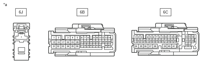
| *a | Front view of wire harness connector
(to Power Distribution Box Assembly) |
- | - |
Disconnect the power distribution box assembly connectors.
Measure the voltage according to the value(s) in the table below.
- Standard Voltage:
Tester Connection Switch Condition Specified Condition 6J-1 - Body ground Ignition switch off 11 to 14 V
Measure the resistance according to the value(s) in the table below.
- Standard Resistance:
Tester Connection Condition Specified Condition 6B-44 - Body ground Always Below 1 Ω 6C-25 - Body ground Always Below 1 Ω
- Result:
Proceed to OK NG
OK
NG
Disconnect the 6F power distribution box assembly connector.
Disconnect the N2 radio setting condenser (noise filter) connector.
Disconnect the R2 back door glass (defogger wire) connector.
Measure the resistance according to the value(s) in the table below.
- Standard Resistance:
Tester Connection Condition Specified Condition 6F-43 - R2-1 (B) Always Below 1 Ω 6F-43 or R2-1 (B) - Body ground Always 10 kΩ or higher
- Result:
Proceed to OK NG
OK
NG
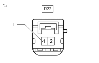
| *a | Front view of wire harness connector
(to Back Door Glass [Defogger Wire]) |
Disconnect the back door glass (defogger wire) connector.
Measure the resistance according to the value(s) in the table below.
- Standard Resistance:
Tester Connection Condition Specified Condition R22-1 (L) - Body ground Always Below 1 Ω
- Result:
Proceed to OK NG
OK
NG
Check the air conditioning system.
for HV Model:
for Gasoline Model:
- HINT:
-
Both the window defogger system operation signal and air conditioning system operation signal are transmitted to the air conditioning amplifier assembly via the same communication line.
- OK:
The air conditioning system operates normally.
- Result:
Proceed to OK NG
OK
NG
for HV Model:
for Gasoline Model:
Check that the indicator illuminates when the defogger switch is on.
- OK:
Defogger indicator illuminates.
- Result:
Proceed to OK NG
OK
NG
Using the GTS, perform the Active Test.
- Body Electrical > Air Conditioner > Active Test
-
Tester Display Measurement Item Control Range Diagnostic Note Rear Defogger Relay RR DEF relay OFF or ON -
- Body Electrical > Air Conditioner > Active Test
-
Tester Display Rear Defogger Relay - 50004 450 7
- OK:
Back door glass (defogger wire) warms up.
- Result:
Proceed to OK NG
OK
NG