LIGHTING (EXT) LIGHTING SYSTEM Automatic High Beam System does not Operate or Operation Indicator does not Illuminate
DESCRIPTION
The main body ECU (multiplex network body ECU) controls the automatic high beam system based on signals received from the forward recognition camera.
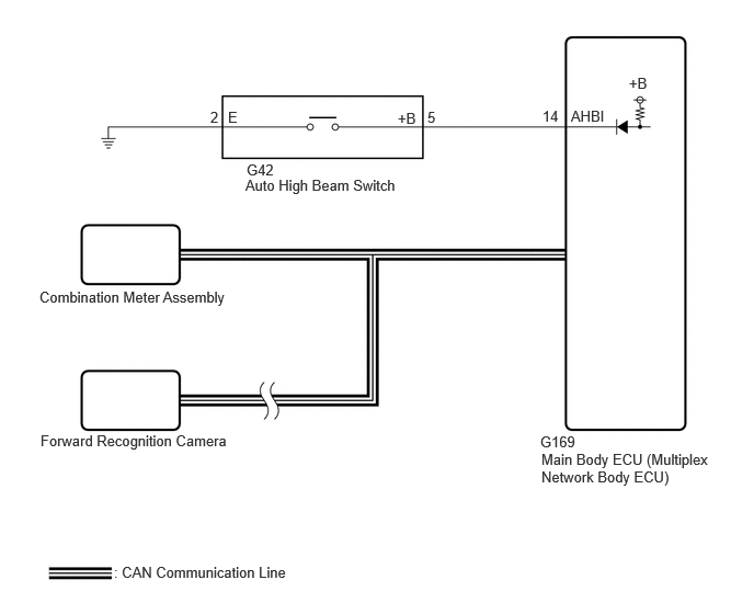
WIRING DIAGRAM
CAUTION / NOTICE / HINT
- NOTICE:
- ·
First, confirm that there is no malfunction in the front radar sensor system.
·w/ Smart Entry and Start System:
Before replacing the main body ECU (multiplex network body ECU), refer to Service Bulletin.
·When replacing the combination meter assembly, always replace it with a new one. If a combination meter assembly which was installed to another vehicle is used, the information stored in it will not match the information from the vehicle and a DTC may be stored.
·Before troubleshooting, make sure that the low beam headlights and high beam headlights operate normally.
·If the windshield glass is dirty, fogged up or has an oily film, the forward recognition camera may not operate properly, affecting the operation of systems that use the forward recognition camera.
·When replacing the forward recognition camera, always replace it with a new one. If a forward recognition camera which was installed to another vehicle is used, the information stored in the forward recognition camera will not match the information from the vehicle. As a result, a DTC may be stored.
·When the forward recognition camera is replaced with a new one, make sure to read Before Starting Adjustment, then perform optical axis alignment for the forward recognition camera and clear the vehicle control history for each system.
- HINT:
-
Forward recognition camera axis alignment can be performed by using either One Time Recognition, Sequential Recognition or Driving Adjustment.
-
One Time Recognition: Click hereEngine / Hybrid System>CRUISE CONTROL>FRONT CAMERA>TARGET ADJUSTMENT(ONE TIME RECOGNITION)202409,999999,_51,_083055,_0401005,RM100000002NTD0,
-
Sequential Recognition: Click hereEngine / Hybrid System>CRUISE CONTROL>FRONT CAMERA>TARGET ADJUSTMENT(SEQUENTIAL RECOGNITION)202409,999999,_51,_083055,_0401005,RM100000002NTD3,
-
Driving Adjustment: Click hereEngine / Hybrid System>CRUISE CONTROL>FRONT CAMERA>DRIVING ADJUSTMENT202409,999999,_51,_083055,_0401005,RM100000002NTD4,
PROCEDURE
Check for vehicle control history.
- Body Electrical > Front Recognition Camera (Front Lighting Control) > Utility
-
Tester Display Vehicle Control History (RoB) - 50005 433 55
- Result:
Result Proceed to X204E is not output A X204E is output B
A
B
Check the operation of the automatic high beam indicator light.
Turn the ignition switch to ON.
Turn the light control switch to the AUTO or HEAD position.
Cover the automatic light control sensor to turn the low beam headlights on.
Move the dimmer switch to the low position.
Press the auto high beam switch.
- Result:
Result Proceed to OK (The automatic high beam indicator light and the auto high beam switch indicator illuminate) A NG (Automatic high beam indicator light does not illuminate) B NG (Auto high beam switch indicator does not illuminate) C NG (Automatic high beam indicator light and auto high beam switch indicator do not operate) D
A
B
C
D
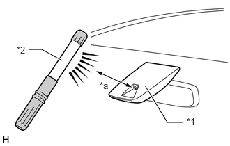
| *1 | Forward Recognition Camera
(Automatic High Beam Sensor) |
| *2 | Work Light or Equivalent |
| *a | 100 mm (3.94 in.) or less |
Shine a light on the automatic high beam sensor.
- HINT:
-
If troubleshooting is being performed in a bright area, such as outside on a sunny day, it will not be necessary to perform this step.
Connect the GTS to the DLC3.
Turn the ignition switch to ON.
Turn the GTS on.
Enter the following menus: Body Electrical / Main Body / Data List.
Read the Data List according to the display on the GTS.
- Body Electrical > Main Body > Data List
-
Tester Display Measurement Item Range Normal Condition Diagnostic Note Automatic High Beam Headlights Sensor Detection Status Automatic high beam sensor current state Undetected, N/A, No sens, Headlight, Taillight, Speed, Daytime, Village, Other sens, Change, Out of aim, SAE Mod, Aim adjust or LIN Err Condition can be displayed -
- Body Electrical > Main Body > Data List
-
Tester Display Automatic High Beam Headlights Sensor Detection Status - 50003 449 119
- OK:
"Daytime" is displayed on the GTS.
- Result:
Proceed to OK NG
OK
NG
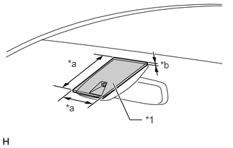
| *1 | Cardboard or Equivalent Object |
| *a | 150 mm (5.91 in.) or more |
| *b | 3 mm (0.118 in.) or more |
Cover the automatic high beam sensor with an opaque object, such as cardboard.
- NOTICE:
- ·
Make sure that there is no clearance between the cardboard or equivalent object and the area of the windshield glass in front of the automatic high beam sensor.
·If there is any clearance, light may shine on the automatic high beam sensor and the value of the Data List will not change.
Connect the GTS to the DLC3.
Turn the ignition switch to ON.
Turn the GTS on.
Enter the following menus: Body Electrical / Main Body / Data List.
Read the Data List according to the display on the GTS.
- HINT:
-
As it may take time for the values in the Data List to change, wait at least 10 seconds before reading the Data List.
- Body Electrical > Main Body > Data List
-
Tester Display Measurement Item Range Normal Condition Diagnostic Note Automatic High Beam Headlights Sensor Detection Status Automatic high beam sensor current state Undetected, N/A, No sens, Headlight, Taillight, Speed, Daytime, Village, Other sens, Change, Out of aim, SAE Mod, Aim adjust or LIN Err Condition can be displayed -
- Body Electrical > Main Body > Data List
-
Tester Display Automatic High Beam Headlights Sensor Detection Status - 50003 449 119
- OK:
"Speed" is displayed on the GTS.
- Result:
Proceed to OK NG
OK
NG
Using the GTS, read the Data List.
- Chassis > Front Recognition Camera > Data List
-
Tester Display Measurement Item Range Normal Condition Diagnostic Note Front Recognition Camera High Temperature 2 Whether high temperature malfunction of forward recognition camera exists or not Not High Temperature or High Temperature Not High Temperature: Approximately 65°C (149°F) or less
High Temperature: Approximately 65°C (149°F) or higherIf this item is "High Temperature", the automatic high beam system will be temporarily unavailable. If this does not improve even if the inside of the vehicle is left cooled for at least 10 minutes, the forward recognition camera may be malfunctioning.
- HINT:
-
In summertime, the windshield glass may reach 100°C (212°F) or higher
- Chassis > Front Recognition Camera > Data List
-
Tester Display Front Recognition Camera High Temperature 2 - 50003 430 13
- OK:
Normal condition listed above is displayed.
- HINT:
-
When "High Temperature" is displayed, move the vehicle to a cool area and turn the ignition switch off to allow the temperature of the front recognition camera to decrease.
- Result:
Proceed to OK NG
OK
NG
Choose the model to be inspected.
- Result:
Result Proceed to Combination meter assembly for 4.2 inch multi-information display type A Combination meter assembly except 4.2 inch multi-information display type B
A
B
Connect the GTS to the DLC3.
Turn the ignition switch to ON.
Turn the GTS on.
Enter the following menus: Body Electrical / Combination Meter / Active Test.
Perform the Active Test according to the display on the GTS.
- Body Electrical > Combination Meter > Active Test
-
Tester Display Measurement Item Control Range Diagnostic Note Automatic High Beam Indicator (Green) Automatic high beam indicator light OFF or ON -
- Body Electrical > Combination Meter > Active Test
-
Tester Display Automatic High Beam Indicator (Green) - 50004 409 35
- OK:
The automatic high beam indicator illuminates and turns off.
- Result:
Proceed to OK NG
OK
NG
Check the meter / gauge system normally.
for GTMC Made: Click hereVehicle Interior>METER / GAUGE / DISPLAY>METER / GAUGE SYSTEM (for GTMC Made)>HOW TO PROCEED WITH TROUBLESHOOTING202405,999999,_58,_083097,_0694857,RM100000002LUOC,
for SFTM Made: Click hereVehicle Interior>METER / GAUGE / DISPLAY>METER / GAUGE SYSTEM (for SFTM Made)>HOW TO PROCEED WITH TROUBLESHOOTING202405,999999,_58,_083097,_0694858,RM100000002LUR9,
- OK:
The meter / gauge system normally.
- Result:
Proceed to OK NG
OK
NG
for GTMC Made: Click hereVehicle Interior>METER / GAUGE / DISPLAY>METER / GAUGE SYSTEM (for GTMC Made)>HOW TO PROCEED WITH TROUBLESHOOTING202405,999999,_58,_083097,_0694857,RM100000002LUOC,
for SFTM Made: Click hereVehicle Interior>METER / GAUGE / DISPLAY>METER / GAUGE SYSTEM (for SFTM Made)>HOW TO PROCEED WITH TROUBLESHOOTING202405,999999,_58,_083097,_0694858,RM100000002LUR9,
Connect the GTS to the DLC3.
Turn the ignition switch to ON.
Turn the GTS on.
Enter the following menus: Body Electrical / Main Body / Data List.
Read the Data List according to the display on the GTS.
- Body Electrical > Main Body > Data List
-
Tester Display Measurement Item Range Normal Condition Diagnostic Note Auto High Beam Main Switch Auto high beam switch signal OFF or ON OFF: Auto high beam switch not pressed
ON: Auto high beam switch pressed-
- Body Electrical > Main Body > Data List
-
Tester Display Auto High Beam Main Switch - 50003 123 274
- OK:
Normal conditions listed above are displayed.
- Result:
Proceed to OK NG
OK
NG
Connect the GTS to the DLC3.
Turn the ignition switch to ON.
Turn the GTS on.
Enter the following menus: Body Electrical / Main Body / Data List.
Read the Data List according to the display on the GTS.
- Body Electrical > Main Body > Data List
-
Tester Display Measurement Item Range Normal Condition Diagnostic Note Auto H Beam STS0 Automatic high beam sensor current state Undetec, CAM NA, No sens, Hlight, Taillgt, Speed, Daytime, Village, Malfunc, Delay, Aim Lmt, SAE Mod, Undefin or LIN Err Condition can be displayed -
- Body Electrical > Main Body > Data List
-
Tester Display Auto H Beam STS0 - 50003 123 169
- OK:
"Daytime" or "Speed" is displayed on the GTS.
- Result:
Proceed to OK NG
OK
NG
Remove the auto high beam switch.
Inspect the auto high beam switch.
- Result:
Proceed to OK NG
OK
NG
Disconnect the G42 auto high beam switch connector.
Disconnect the G169 main body ECU (multiplex network body ECU) connector.
Measure the resistance according to the value(s) in the table below.
- Standard Resistance:
Tester Connection Condition Specified Condition G42-5 (+B) - G169-14 (AHBI) Always Below 1 Ω G42-5 (+B) or G169-14 (AHBI) - Body ground Always 10 kΩ or higher G42-2 (E) - Body ground Always Below 1 Ω
- Result:
Proceed to OK NG
OK
NG