RM36D0EC _54 Brake _083077 BRAKE CONTROL / DYNAMIC CONTROL SYSTEMS _0402316 ELECTRONICALLY CONTROLLED BRAKE SYSTEM(for Gasoline Model) J

BRAKE CONTROL / DYNAMIC CONTROL SYSTEMS  ELECTRONICALLY CONTROLLED BRAKE SYSTEM(for Gasoline Model)  Downhill Assist Control Indicator Light does not Come ON  


DESCRIPTION

Even if the downhill assist control switch is pressed, the downhill assist control indicator light blinks and downhill assist control does not activate under the following conditions:

·

1st gear of S mode or not R.

·

The vehicle speed is 25 km/h (16 mph) or more.

·

The brake system is malfunctioning.

·

Temperature of the brake actuator assembly increases and the downhill assist control is temporarily canceled.


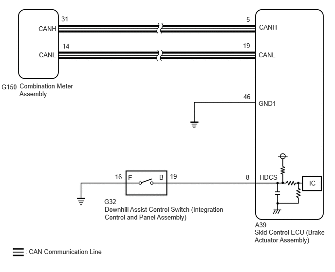
WIRING DIAGRAM

Except 12.3 Inch TFT Display Type:
C408613E01
5.542,0.5 6.156,0.698 0.615,0.198 10 false CANH 0.823,0.531 1.24,0.729 0.417,0.198 10 false CANH 5.271,0.333 5.469,0.583 0.198,0.25 10 false 5 1.333,0.323 1.531,0.573 0.198,0.25 10 false 9 0.833,1.094 1.25,1.292 0.417,0.198 10 false CANL 5.531,1.094 5.948,1.292 0.417,0.198 10 false CANL 5.198,0.896 5.396,1.146 0.198,0.25 10 false 19 1.333,0.906 1.531,1.156 0.198,0.25 10 false 25 5.531,2.135 5.948,2.333 0.417,0.198 10 false GND1 5.208,1.99 5.406,2.24 0.198,0.25 10 false 46 0.083,1.76 0.469,2 0.385,0.24 10 false G18 5.552,3.719 6.052,4.01 0.5,0.292 10 false HDCS 5.26,3.719 5.458,3.969 0.198,0.25 10 false 8 2.24,4.406 4.833,4.792 2.594,0.385 10 false Downhill Assist Control Switch (Integration Control and Panel Assembly) 2.229,4.24 2.594,4.49 0.365,0.25 10 false G32 5.458,4.74 5.823,4.99 0.365,0.25 10 false A39 5.448,4.896 7.01,5.313 1.563,0.417 10 false Skid Control ECU (Brake Actuator Assembly) 0.542,5.313 2.708,5.646 2.167,0.333 10 false : CAN Communication Line 0.417,1.76 1.594,2.198 1.177,0.438 10 false Combination Meter Assembly 2.458,3.708 2.76,3.958 0.302,0.25 10 false 16 3.635,3.698 3.927,3.958 0.292,0.26 10 false 19 6.615,3.844 6.969,4.115 0.354,0.271 10 false IC 3.406,3.719 3.698,3.979 0.292,0.26 10 false B 2.74,3.729 3.031,3.99 0.292,0.26 10 false E

for 12.3 Inch TFT Display Type:
C408613E07
5.542,0.5 6.156,0.698 0.615,0.198 10 false CANH 0.823,0.531 1.24,0.729 0.417,0.198 10 false CANH 5.271,0.333 5.469,0.583 0.198,0.25 10 false 5 1.313,0.323 1.51,0.573 0.198,0.25 10 false 31 0.833,1.094 1.25,1.292 0.417,0.198 10 false CANL 5.531,1.094 5.948,1.292 0.417,0.198 10 false CANL 5.198,0.896 5.396,1.146 0.198,0.25 10 false 19 1.333,0.906 1.531,1.156 0.198,0.25 10 false 14 5.531,2.135 5.948,2.333 0.417,0.198 10 false GND1 5.208,1.99 5.406,2.24 0.198,0.25 10 false 46 0.031,1.781 0.417,2.021 0.385,0.24 10 false G150 5.552,3.719 6.052,4.01 0.5,0.292 10 false HDCS 5.26,3.719 5.458,3.969 0.198,0.25 10 false 8 2.24,4.406 4.833,4.792 2.594,0.385 10 false Downhill Assist Control Switch (Integration Control and Panel Assembly) 2.229,4.24 2.594,4.49 0.365,0.25 10 false G32 5.458,4.74 5.823,4.99 0.365,0.25 10 false A39 5.448,4.896 7.01,5.313 1.563,0.417 10 false Skid Control ECU (Brake Actuator Assembly) 0.542,5.313 2.708,5.646 2.167,0.333 10 false : CAN Communication Line 0.417,1.76 1.594,2.198 1.177,0.438 10 false Combination Meter Assembly 2.458,3.708 2.76,3.958 0.302,0.25 10 false 16 3.635,3.698 3.927,3.958 0.292,0.26 10 false 19 6.615,3.844 6.969,4.115 0.354,0.271 10 false IC 3.406,3.719 3.698,3.979 0.292,0.26 10 false B 2.74,3.729 3.031,3.99 0.292,0.26 10 false E

CAUTION / NOTICE / HINT

NOTICE:

After replacing the skid control ECU (brake actuator assembly), perform acceleration sensor zero point calibration and store system information memorization.

Click hereBrake>BRAKE CONTROL / DYNAMIC CONTROL SYSTEMS>ELECTRONICALLY CONTROLLED BRAKE SYSTEM (for Gasoline Model)>UTILITY


PROCEDURE

1.INSPECT INTEGRATION CONTROL AND PANEL ASSEMBLY
a.

Turn the ignition switch off.


b.

Remove the downhill assist control switch (integration control and panel assembly).

Click hereBrake>BRAKE CONTROL / DYNAMIC CONTROL SYSTEMS>DOWNHILL ASSIST CONTROL SWITCH>REMOVAL


c.

Inspect the downhill assist control switch (integration control and panel assembly).

Click hereBrake>BRAKE CONTROL / DYNAMIC CONTROL SYSTEMS>DOWNHILL ASSIST CONTROL SWITCH>INSPECTION

OK:

The downhill assist control switch operates normally.


Result:
Proceed to
OK
NG


OK

2.CHECK HARNESS AND CONNECTOR (BRAKE ACTUATOR ASSEMBLY - INTEGRATION CONTROL AND PANEL ASSEMBLY)

NG

2.CHECK HARNESS AND CONNECTOR (BRAKE ACTUATOR ASSEMBLY - INTEGRATION CONTROL AND PANEL ASSEMBLY)
a.

Disconnect the A39 skid control ECU (brake actuator assembly) connector.


b.

Measure the resistance according to the value(s) in the table below.

Standard Resistance:
Tester Connection Condition Specified Condition
A39-8 (HDCS) - G32-19 (B) Always Below 1 Ω
A39-8 (HDCS) or G32-19 (B) - Body ground Always 10 kΩ or higher
G32-16 (E) - Body ground Always Below 1 Ω


Result:
Proceed to
OK
NG


OK

3.INSPECT COMBINATION METER ASSEMBLY

NG

REPAIR OR REPLACE HARNESS OR CONNECTOR

3.INSPECT COMBINATION METER ASSEMBLY
a.

Turn the ignition switch off.


b.

Perform the Active Test of the combination meter assembly using the GTS.

for SFTM Made: Click hereVehicle Interior>METER / GAUGE / DISPLAY>METER / GAUGE SYSTEM (for SFTM Made)>DATA LIST / ACTIVE TEST

for GTMC Made: Click hereVehicle Interior>METER / GAUGE / DISPLAY>METER / GAUGE SYSTEM (for GTMC Made)>DATA LIST / ACTIVE TEST

Body Electrical > Combination Meter > Active Test
Tester Display
Downhill Assist Control Indicator
50004 409 119

c.

Check the combination meter assembly.

OK:

The Downhill assist control indicator light turns on or off in accordance with the GTS.


Result:
Proceed to
OK
NG


OK

NG