GF1A TRANSFER / 4WD / AWD DYNAMIC TORQUE CONTROL AWD SYSTEM AWD Control Switch Circuit
WIRING DIAGRAM
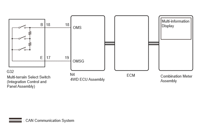
PROCEDURE
Read the Data List according to the display on the GTS.
- Powertrain > Engine > Data List
-
Tester Display Measurement Item Range Normal Condition Diagnostic Note Off-road Guidance Status Off road mode status Normal, Grass & Snow, Mud & Sand, Loose Rock, Mogul or Rock & Dirt - -
- Powertrain > Engine > Data List
-
Tester Display Off-road Guidance Status - 50003 372 1098
Operate the multi-terrain select switch (integration control and panel assembly) and check that the Data List display and multi-information display message change according to switch operation.
- OK:
Multi-terrain Select Switch (Integration Control and Panel Assembly) Operation Data List Display Multi-information Display Message NORMAL Normal NORMAL MUD&SAND Mud & Sand MUD&SAND ROCK&DIRT Rock & Dirt ROCK&DIRT
- Result:
Result Proceed to When the switch is operated, the Data List display and message do not change A When the switch is operated, the Data List display changes, but message do not change B When the switch is operated, the Data List display and message change normally C
A
B
for SFTM Made: Click hereVehicle Interior>METER / GAUGE / DISPLAY>METER / GAUGE SYSTEM (for SFTM Made)>HOW TO PROCEED WITH TROUBLESHOOTING202405,999999,_58,_083097,_0694858,RM100000002LUR9,
for GTMC Made: Click hereVehicle Interior>METER / GAUGE / DISPLAY>METER / GAUGE SYSTEM (for GTMC Made)>HOW TO PROCEED WITH TROUBLESHOOTING202405,999999,_58,_083097,_0694857,RM100000002LUOC,
C
Inspect the multi-terrain select switch (integration control and panel assembly).
- Result:
Proceed to OK NG
OK
NG
Turn the ignition switch off.
Disconnect the N4 4WD ECU assembly connector.
Disconnect the G32 multi-terrain select switch (integration control and panel assembly) connector.
Measure the resistance according to the value(s) in the table below.
- Standard Resistance:
Tester Connection Condition Specified Condition N4-18 (OMS) - G32-18 (B) Always Below 1 Ω N4-19 (OMSG) - G32-17 (E) Always Below 1 Ω N4-18 (OMS) or G32-18 (B) - Body ground Always 10 kΩ or higher N4-19 (OMSG) or G32-17 (E) - Body ground Always 10 kΩ or higher N4-18 (OMS) or G32-18 (B) - N4-19 (OMSG) or G32-17 (E) Always 10 kΩ or higher
- Result:
Proceed to OK NG
OK
NG