HYBRID / BATTERY CONTROL HYBRID CONTROL SYSTEM P310711 Lost Communication with Airbag System Control Module Circuit Short to Ground
DESCRIPTION
The hybrid vehicle control ECU assembly detects a problem in the collision signal line from the airbag ECU assembly and alerts the driver.
| DTC No. | Detection Item | DTC Detection Condition | Trouble Area | MIL | Warning Indicate | Note |
|---|---|---|---|---|---|---|
| P310711 | Lost Communication with Airbag System Control Module Circuit Short to Ground | Short to ground in the communication circuit:
Communication from the airbag sensor assembly stopped and Circuit Low has been detected for a certain period. (1 trip detection logic) |
·
Wire harness or connector ·
Airbag sensor assembly ·
Hybrid vehicle control ECU assembly |
Does not come on | Master Warning:
Comes on |
SAE Code:
P3107 |
| DTC No. | Data List |
|---|---|
| P310711 | Airbag Status (Collision) |
CONFIRMATION DRIVING PATTERN
- HINT:
-
After repair has been completed, clear the DTCs and then check that the vehicle has returned to normal by performing the following All Readiness check procedure.
Connect the GTS to the DLC3.
Turn the power switch on (IG) and turn the GTS on.
Clear the DTCs (even if no DTCs are stored, perform the clear DTC procedure).
Turn the power switch off and wait for 2 minutes or more.
Turn the power switch on (IG) and turn the GTS on.
With power switch on (IG) and wait for 2 minutes or more.
Enter the following menus: Powertrain / Hybrid Control / Utility / All Readiness.
Check the DTC judgment result.
- HINT:
- ·
If the judgment result shows NORMAL, the system is normal.
·If the judgment result shows ABNORMAL, the system has a malfunction.
·If the judgment result shows INCOMPLETE, perform driving pattern again.
WIRING DIAGRAM
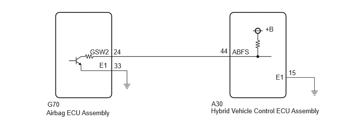
PROCEDURE
Connect the GTS to the DLC3.
Turn the power switch on (IG).
Enter the following menus: Body Electrical / SRS Airbag / Trouble Codes.
Check for DTCs.
- Body Electrical > SRS Airbag > Trouble Codes
- 50001 188
- Result:
Result Proceed to Airbag system DTCs are not output. A Airbag system DTCs are output. B
Turn the power switch off.
A
B
for GTMC Made: Click hereVehicle Interior>SUPPLEMENTAL RESTRAINT SYSTEMS>AIRBAG SYSTEM (for GTMC Made)>DIAGNOSTIC TROUBLE CODE CHART202405,999999,_58,_083100,_0694959,RM100000002LV1G,
for SFTM Made: Click hereVehicle Interior>SUPPLEMENTAL RESTRAINT SYSTEMS>AIRBAG SYSTEM (for SFTM Made)>DIAGNOSTIC TROUBLE CODE CHART202409,999999,_58,_083100,_0694957,RM100000002NSO5,
Connect an oscilloscope between the hybrid vehicle control ECU assembly terminals specified in the table below.
Turn the power switch on (READY).
Measure the waveform.
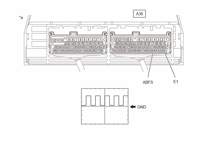
| *a | Component with harness connected
(Hybrid Vehicle Control ECU Assembly) |
- | - |
| Item | Contents |
|---|---|
| Terminal | A30-44 (ABFS) - A30-15 (E1) |
| Equipment Setting | 5 V/DIV., 150 ms./DIV. |
| Condition | Power switch on (READY) |
- Result:
Result Proceed to The waveform appears as shown in the illustration. A The waveform differs from the one shown in the illustration. B
Turn the power switch off.
A
B
- Result:
Proceed to NEXT
NEXT
Connect the GTS to the DLC3.
Turn the power switch on (IG).
Enter the following menus: Powertrain / Hybrid Control / Trouble Codes.
Check for DTCs.
- Powertrain > Hybrid Control > Trouble Codes
- 50001 397
- Result:
Result Proceed to P310711 is not output. A P310711 is output. B
Turn the power switch off.
A
B
- Result:
Proceed to OK NG
OK
NG
Disconnect the G70 airbag ECU assembly connector.
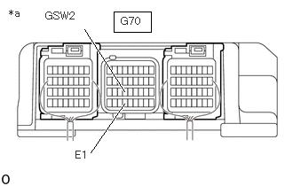
| *a | Component without harness connected
(Airbag ECU Assembly) |
Measure the resistance according to the value(s) in the table below.
- Standard Resistance:
Tester Connection Condition Specified Condition G70-24 (GSW2) - G70-33 (E1) Power switch off 10 kΩ or higher
Reconnect the G70 airbag ECU assembly connector.
- Result:
Proceed to OK NG
OK
NG
Disconnect the A30 hybrid vehicle control ECU assembly connector.
Disconnect the G70 airbag ECU assembly connector.
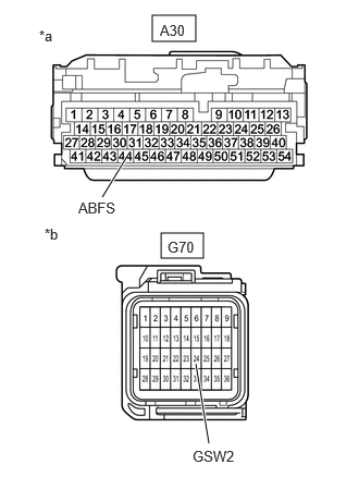
| *a | Front view of wire harness connector
(to Hybrid Vehicle Control ECU Assembly) |
| *b | Front view of wire harness connector
(to Airbag ECU Assembly) |
Measure the resistance according to the value(s) in the table below.
- Standard Resistance:
Tester Connection Condition Specified Condition A30-44 (ABFS) or G70-24 (GSW2) - Body ground and other terminals Power switch off 10 kΩ or higher
Reconnect the G70 airbag ECU assembly connector.
Reconnect the A30 hybrid vehicle control ECU assembly connector.
- Result:
Proceed to OK NG
OK
NG