HYBRID / BATTERY CONTROL HYBRID CONTROL SYSTEM P0AE411 Hybrid/EV Battery Precharge Contactor Circuit Short to Ground
DESCRIPTION
The SMRs (System Main Relays) are the relays that connect or disconnect the high-voltage system in accordance with commands from the hybrid vehicle control ECU assembly.
There are 3 SMRs and 1 system main resistor. SMRB, SMRP, SMRG and the system main resistor are located in the HV battery junction block assembly.
To connect to the high voltage power system, the vehicle will first turn on SMRP and SMRB to charge the vehicle through the system main resistor. Then, SMRP will be turned off after SMRG is turned on. To shut off the high voltage power system, SMRB and SMRG are turned off.
| DTC No. | Detection Item | DTC Detection Condition | Trouble Area | MIL | Warning Indicate | Note |
|---|---|---|---|---|---|---|
| P0AE411 | Hybrid/EV Battery Precharge Contactor Circuit Short to Ground | Short to ground in the SMRP circuit:
Primary circuit of SMRP is malfunctioning. (2 trip detection logic) |
·
Wire harness or connector ·
HV battery junction block assembly ·
Hybrid vehicle control ECU assembly |
Does not come on | Master Warning:
Comes on |
SAE Code:
P0AE6 |
| DTC No. | Data List |
|---|---|
| P0AE411 | ·
VL-Voltage before Boosting ·
VH-Voltage after Boosting ·
Hybrid/EV Battery Voltage ·
SMRP Status ·
SMRB Status ·
SMRG Status ·
SMRP Control Status ·
SMRB Control Status ·
SMRG Control Status ·
Boosting Converter Shutdown Status ·
Generator Inverter Shutdown Status ·
Motor Inverter Shutdown Status |
CONFIRMATION DRIVING PATTERN
- HINT:
-
After repair has been completed, clear the DTC and then check that the vehicle has returned to normal by performing the following All Readiness check procedure.
Connect the GTS to the DLC3.
Turn the power switch on (IG) and turn the GTS on.
Clear the DTCs (even if no DTCs are stored, perform the clear DTC procedure).
Turn the power switch off and wait for 2 minutes or more.
Turn the power switch on (READY) and wait for 30 seconds or more.
Turn the power switch off and wait for 2 minutes or more.
Turn the power switch on (IG) and turn the GTS on.
Enter the following menus: Powertrain / Hybrid Control / Utility / All Readiness.
Check the DTC judgment result.
- HINT:
- ·
If the judgment result shows NORMAL, the system is normal.
·If the judgment result shows ABNORMAL, the system has a malfunction.
·If the judgment result shows INCOMPLETE, perform driving pattern again.
WIRING DIAGRAM
Refer to the wiring diagram for the HV battery high-voltage line circuit.
CAUTION / NOTICE / HINT
- CAUTION:
-
Refer to the precautions before inspecting high voltage circuit.
- HINT:
-
If DTC P0AE411 is output, the power switch cannot be turned on (READY).
PROCEDURE
Disconnect the A30 hybrid vehicle control ECU assembly connector.
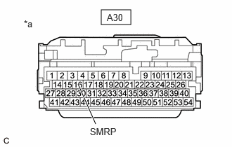
| *a | Front view of wire harness connector
(to Hybrid Vehicle Control ECU Assembly) |
Measure the resistance according to the value(s) in the table below.
- Standard Resistance:
Tester Connection Condition Specified Condition A30-16 (SMRP) - Body ground Power switch off 140 to 290 Ω
Reconnect the A30 hybrid vehicle control ECU assembly connector.
- Result:
Proceed to OK NG
OK
NG
- Result:
Result Proceed to OK A NG (The connector is not connected securely.) B NG (The terminals are not making secure contact or are deformed, or water or foreign matter exists in the connector.) C
A
B
C
- CAUTION:
-
Be sure to wear insulated gloves.
Check that the service plug grip is not installed.
- NOTICE:
-
After removing the service plug grip, do not turn the power switch on (READY), unless instructed by the repair manual because this may cause a malfunction.
Remove the No. 1 HV battery cover panel RH.
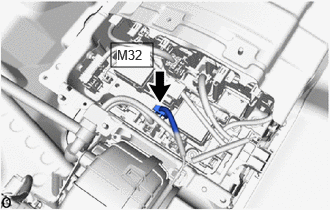
Disconnect the M32 HV battery junction block assembly connector.
Disconnect the A30 hybrid vehicle control ECU assembly connector.
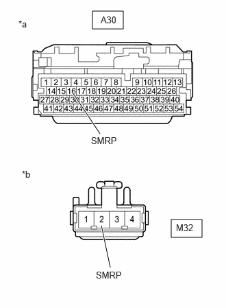
| *a | Front view of wire harness connector
(to Hybrid Vehicle Control ECU Assembly) |
| *b | Front view of wire harness connector
(to HV Battery Junction Block Assembly) |
Measure the resistance according to the value(s) in the table below.
- Standard Resistance:
Tester Connection Condition Specified Condition A30-16 (SMRP) or M32-2 (SMRP) - Body ground and other terminals Power switch off 10 kΩ or higher
Reconnect the A30 hybrid vehicle control ECU assembly connector.
Reconnect the M32 HV battery junction block assembly connector.
Install the No. 1 HV battery cover panel RH.
- Result:
Proceed to OK NG
OK
NG