POWER ASSIST SYSTEMS POWER STEERING SYSTEM Drive Mode Select Switch Circuit
DESCRIPTION
The electronic throttle and the EPS character change by the operation of the drive mode select switch (integration control and panel assembly).
WIRING DIAGRAM
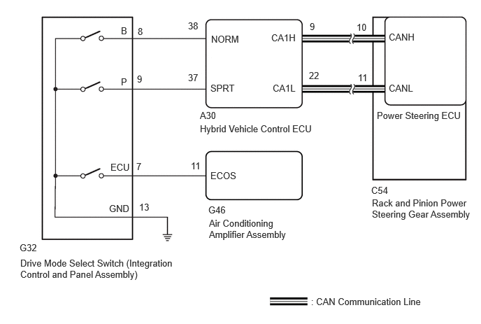
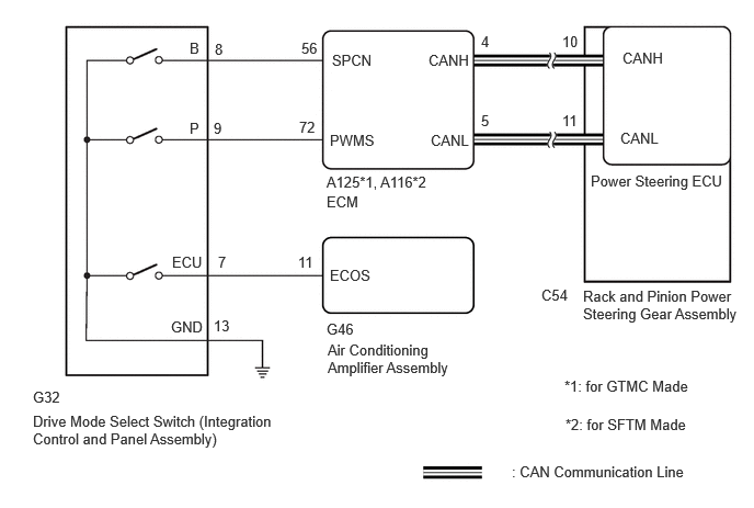
PROCEDURE
Check each symptom by checking the suspected areas in the table below.
- Result:
Result Proceed to SPORT mode or NORMAL mode is abnormal. A ECO mode is abnormal. B
A
B
for HV Model: Click hereVehicle Interior>HEATING / AIR CONDITIONING>AIR CONDITIONING SYSTEM (for HV Model)>ECO Switch Circuit202409,999999,_58,_083104,_0402829,RM100000002NSK4,
for Gasoline Model: Click hereVehicle Interior>HEATING / AIR CONDITIONING>AIR CONDITIONING SYSTEM (for Gasoline Model)>ECO Switch Circuit202409,999999,_58,_083104,_0402828,RM100000002NSIG,
Check for DTCs.
for GTMC Made HV Model: Click herePower Source / Network>NETWORKING>CAN COMMUNICATION SYSTEM (for GTMC Made HV Model)>HOW TO PROCEED WITH TROUBLESHOOTING202409,999999,_57,_083091,_0694855,RM100000002NTBR,
for GTMC Made Gasoline Model: Click herePower Source / Network>NETWORKING>CAN COMMUNICATION SYSTEM (for GTMC Made Gasoline Model)>HOW TO PROCEED WITH TROUBLESHOOTING202409,999999,_57,_083091,_0694856,RM100000002NTA4,
for SFTM Made HV Model: Click herePower Source / Network>NETWORKING>CAN COMMUNICATION SYSTEM (for SFTM Made HV Model)>HOW TO PROCEED WITH TROUBLESHOOTING202409,999999,_57,_083091,_0694853,RM100000002NT0M,
for SFTM Made Gasoline Model: Click herePower Source / Network>NETWORKING>CAN COMMUNICATION SYSTEM (for SFTM Made Gasoline Model)>HOW TO PROCEED WITH TROUBLESHOOTING202409,999999,_57,_083091,_0694854,RM100000002NUBH,
- Result:
Result Proceed to CAN communication system DTCs are not output. A CAN communication system DTCs are output. B
A
B
for GTMC Made HV Model: Click herePower Source / Network>NETWORKING>CAN COMMUNICATION SYSTEM (for GTMC Made HV Model)>HOW TO PROCEED WITH TROUBLESHOOTING202409,999999,_57,_083091,_0694855,RM100000002NTBR,
for GTMC Made Gasoline Model: Click herePower Source / Network>NETWORKING>CAN COMMUNICATION SYSTEM (for GTMC Made Gasoline Model)>HOW TO PROCEED WITH TROUBLESHOOTING202409,999999,_57,_083091,_0694856,RM100000002NTA4,
for SFTM Made HV Model: Click herePower Source / Network>NETWORKING>CAN COMMUNICATION SYSTEM (for SFTM Made HV Model)>HOW TO PROCEED WITH TROUBLESHOOTING202409,999999,_57,_083091,_0694853,RM100000002NT0M,
for SFTM Made Gasoline Model: Click herePower Source / Network>NETWORKING>CAN COMMUNICATION SYSTEM (for SFTM Made Gasoline Model)>HOW TO PROCEED WITH TROUBLESHOOTING202409,999999,_57,_083091,_0694854,RM100000002NUBH,
Turn the ignition switch off.
Disconnect the G32 drive mode select switch (integration control and panel assembly) connector.
Measure the resistance according to the value(s) in the table below.
- Standard Resistance:
Tester Connection Condition Specified Condition G32-13 (GND) - Body ground Always Below 1 Ω
- Result:
Proceed to OK NG
OK
NG
Inspect the drive mode select switch (integration control and panel assembly).
for Gasoline Model:
for 2WD: Click hereDrivetrain>K121 (CVT)>COMBINATION SWITCH>INSPECTION202304,999999,_52,_138176,_0579408,RM1000000029EO6,
for AWD: Click hereDrivetrain>K121F (CVT)>COMBINATION SWITCH>INSPECTION202304,999999,_52,_138817,_0584992,RM1000000029ILX,
- Result:
Result Proceed to Drive mode select switch (integration control and panel assembly) is normal (for HV Model) A Drive mode select switch (integration control and panel assembly) is normal (for Gasoline Model) B Drive mode select switch (integration control and panel assembly) is abnormal C
A
B
C
for Gasoline Model:
for 2WD: Click hereDrivetrain>K121 (CVT)>COMBINATION SWITCH>REMOVAL202304,999999,_52,_138176,_0579408,RM1000000029EO1,
for AWD: Click hereDrivetrain>K121F (CVT)>COMBINATION SWITCH>REMOVAL202304,999999,_52,_138817,_0584992,RM1000000029ILW,
Reconnect the G32 drive mode select switch (integration control and panel assembly) connector.
Disconnect the A30 hybrid vehicle control ECU connector.
Measure the resistance according to the value(s) in the table below.
- Standard Resistance:
Tester Connection Condition Specified Condition A30-37 (SPRT) - Body ground SPORT mode switch being turned and held Below 1 Ω A30-37 (SPRT) - Body ground SPORT mode switch not turned 10 kΩ or higher A30-38 (NORM) - Body ground NORMAL mode switch being pushed and held Below 1 Ω A30-38 (NORM) - Body ground NORMAL mode switch not pushed 10 kΩ or higher
- Result:
Proceed to OK NG
OK
NG
Reconnect the G32 drive mode select switch (integration control and panel assembly) connector.
Disconnect the A125*1 or A116*2 ECM connector.
*1: for GTMC Made
*2: for SFTM Made
Measure the resistance according to the value(s) in the table below.
- Standard Resistance:
for GTMC Made: Tester Connection Condition Specified Condition A125-72 (PWMS) - Body ground SPORT mode switch being turned and held Below 1 Ω A125-72 (PWMS) - Body ground SPORT mode switch not turned 10 kΩ or higher A125-56 (SPCN) - Body ground NORMAL mode switch being pushed and held Below 1 Ω A125-56 (SPCN) - Body ground NORMAL mode switch not pushed 10 kΩ or higher
for SFTM Made: Tester Connection Condition Specified Condition A116-72 (PWMS) - Body ground SPORT mode switch being turned and held Below 1 Ω A116-72 (PWMS) - Body ground SPORT mode switch not turned 10 kΩ or higher A116-56 (SPCN) - Body ground NORMAL mode switch being pushed and held Below 1 Ω A116-56 (SPCN) - Body ground NORMAL mode switch not pushed 10 kΩ or higher
- Result:
Proceed to OK NG
OK
for M20C-FKS: Click hereEngine / Hybrid System>M20C-FKS (ENGINE CONTROL)>ECM>REMOVAL202405,999999,_51,_087036,_0418140,RM100000002JM0N,
for M20D-FKS: Click hereEngine / Hybrid System>M20D-FKS (ENGINE CONTROL)>ECM>REMOVAL202409,999999,_51,_083058,_0401822,RM100000002NRO9,
NG