K121 CVT COMBINATION SWITCH INSPECTION
PROCEDURE

 84010D
1.INSPECT INTEGRATION CONTROL AND PANEL ASSEMBLY (COMBINATION SWITCH)
84010D
1.INSPECT INTEGRATION CONTROL AND PANEL ASSEMBLY (COMBINATION SWITCH)
Inspect the NORMAL mode switch:
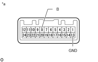
| *a | Component without harness connected
(Integration Control and Panel Assembly (Combination Switch)) |
Measure the resistance according to the value(s) in the table below.
- Standard Resistance:
Tester Connection Condition Specified Condition 8 (B) - 13 (GND) NORMAL mode switch being pushed and held Below 1 Ω NORMAL mode switch not pushed 10 kΩ or higher
If the result is not as specified, replace the integration control and panel assembly (combination switch).
Inspect the SPORT mode switch:
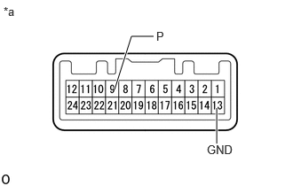
| *a | Component without harness connected
(Integration Control and Panel Assembly (Combination Switch)) |
Measure the resistance according to the value(s) in the table below.
- Standard Resistance:
Tester Connection Condition Specified Condition 9 (P) - 13 (GND) SPORT mode switch being pushed and held Below 1 Ω SPORT mode switch not pushed 10 kΩ or higher
If the result is not as specified, replace the integration control and panel assembly (combination switch).
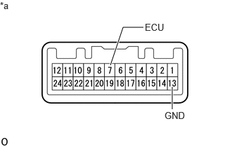
| *a | Component without harness connected
(Integration Control and Panel Assembly (Combination Switch)) |
Inspect the ECO mode switch:
Measure the resistance according to the value(s) in the table below.
- Standard Resistance:
Tester Connection Condition Specified Condition 7 (ECU) - 13 (GND) ECO mode switch being pushed and held Below 1 Ω ECO mode switch not pushed 10 kΩ or higher
If the result is not as specified, replace the integration control and panel assembly (combination switch).
Check that the illumination illuminates.

| *a | Component without harness connected
(Integration Control and Panel Assembly (Combination Switch)) |
Apply battery voltage to the combination switch and check that the switch illuminates.
- OK:
Condition Specified Condition Battery positive (+) → Terminal 12 (ILL+)
Battery negative (-) → Terminal 1 (ILL-)Illuminates
If the result is not as specified, replace the integration control and panel assembly (combination switch).