DOOR / HATCH KICK SENSOR REMOVAL
CAUTION / NOTICE / HINT
The necessary procedures (adjustment, calibration, initialization, or registration) that must be performed after parts are removed, installed, or replaced during the kick door control sensor removal/installation are shown below.
| Replaced Part or Performed Procedure | Necessary Procedures | Effect/Inoperative Function when Necessary Procedures are not Performed | Link |
|---|---|---|---|
| Kick door control sensor | Reset connection history | There are cases where the connection history display differs from the vehicle condition | ( 202409,999999,_59,_083093,_0584672,RM100000002NT2L,) 202409,999999,_59,_083093,_0584672,RM100000002NT2L,)
|
- HINT:
-
When the cable is disconnected / reconnected to the auxiliary battery terminal, systems temporarily stop operating. However, each system has a function that completes learning the first time the system is used.
- ·
Learning completes when vehicle is driven
Effect/Inoperative Function When Necessary Procedures are not Performed Necessary Procedures Link Lane tracing assist system Drive the vehicle straight ahead at 35 km/h (22 mph) or more for 5 second or more. ( 201910,999999,_58,_083101,_0401880,RM100000001JE9I,)
Pre-collision system
- ·
Learning completes when vehicle is operated normally
Effect/Inoperative Function When Necessary Procedures are not Performed Necessary Procedures Link Power back door function Fully close the back door by hand.
- HINT:
-
Initialization is not necessary if the above procedures are performed while the back door is closed.
( 202304,999999,_59,_083093,_0584672,RM1000000029PGT,)
Power door lock control system If the back door is locked and therefore cannot be opened, it is necessary to unlock the back door using the door control switch, electrical key transmitter sub-assembly switch. ( 202409,999999,_58,_083092,_0403003,RM100000002NS90,)
Air conditioning system After the ignition switch is turned to ON, the servo motor standard position is recognized -
| Replaced Part or Performed Procedure | Necessary Procedures | Effect/Inoperative Function when Necessary Procedures are not Performed | Link |
|---|---|---|---|
| Kick door control sensor | Reset connection history | There are cases where the connection history display differs from the vehicle condition | (202409,999999,_59,_083093,_0584672,RM100000002NT2L,)
|
- HINT:
-
When the cable is disconnected / reconnected to the auxiliary battery terminal, systems temporarily stop operating. However, each system has a function that completes learning the first time the system is used.
- ·
Learning completes when vehicle is driven
Effect/Inoperative Function When Necessary Procedures are not Performed Necessary Procedures Link Stop and start system Drive the vehicle until stop and start control is permitted (approximately 5 to 60 minutes). ( 202409,999999,_51,_083056,_0402418,RM100000002NSFO,)
Lane tracing assist system Drive the vehicle straight ahead at 15 km/h (10 mph) or more for 1 second or more. ( 201910,999999,_58,_083101,_0401880,RM100000001JE9I,)
Pre-collision system
- ·
Learning completes when vehicle is operated normally
Effect/Inoperative Function When Necessary Procedures are not Performed Necessary Procedures Link *: w/ Power back door system
Power back door function* Fully close the back door by hand.
- HINT:
-
Initialization is not necessary if the above procedures are performed while the back door is closed.
( 202304,999999,_59,_083093,_0584672,RM1000000029PGT,)
Power door lock control system If the back door is locked and therefore cannot be opened, it is necessary to unlock the back door using the door control switch, electrical key transmitter sub-assembly switch. ( 202409,999999,_58,_083092,_0403003,RM100000002NS90,)
Air conditioning system After the ignition switch is turned to ON, the servo motor standard position is recognized -
PROCEDURE

 1. PRECAUTION
- NOTICE:
-
After turning the ignition switch off, waiting time may be required before disconnecting the cable from the negative (-) auxiliary battery terminal.
2.DISCONNECT CABLE FROM NEGATIVE AUXILIARY BATTERY TERMINAL
- CAUTION:
-
- ·
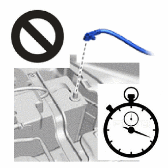
Wait at least 60 seconds after disconnecting the cable from the negative (-) auxiliary battery terminal to disable the SRS system.
·If the airbag deploys for any reason, it may cause a serious accident.
for M20C-FKS:
Click hereGeneral>MAINTENANCE>M20C-FKS BATTERY>REMOVAL202409,999999,_V1,_083136,_0418197,RM100000002NHPI,
for M20D-FKS:
Click hereGeneral>MAINTENANCE>M20D-FKS BATTERY>REMOVAL202409,999999,_V1,_083136,_0403617,RM100000002NHPJ,
52159
3.REMOVE REAR BUMPER COVER
891B1
4.REMOVE KICK DOOR CONTROL BRACKET (for Type A)
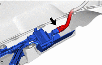
Disconnect the connector.
- NOTICE:
-
Do not touch the terminal of the kick door control sensor connector.
Remove the 3 screws.
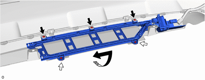

|
Remove in this Direction | 
|
Screw |

|
Clip | - | - |
Remove the 2 clips and kick door control bracket together with the kick door control sensor.
891B1
5.REMOVE KICK DOOR CONTROL BRACKET (for Type B)
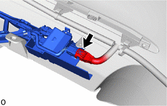
Disconnect the connector.
- NOTICE:
-
Do not touch the terminal of the kick door control sensor connector.
Remove the 3 screws.
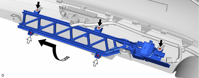
|
|
Remove in this Direction |
|
Screw |
|
|
Clip | - | - |
Remove the 2 clips and kick door control bracket together with the kick door control sensor.
891B2
6.REMOVE KICK DOOR CONTROL SENSOR (for Type A)
Detach the claw and guide and disconnect the antenna cable in the order shown in the illustration.
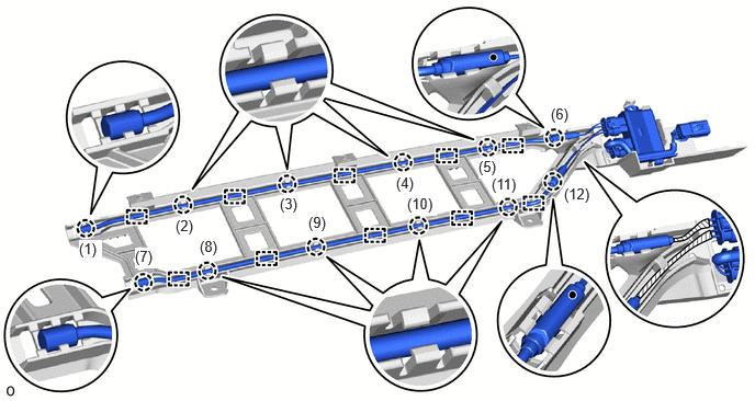
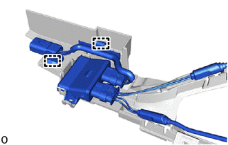
Detach the clamp.
- NOTICE:
- ·
Do not pull strongly on the wire.
·Do not twist the wire.
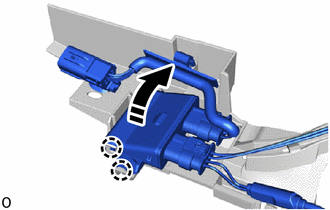
|
|
Remove in this Direction |
Detach the claw in the direction indicated by the arrow as shown in the illustration.
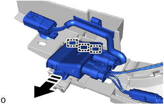
|
|
Remove in this Direction |
Detach the guide and remove the kick door control sensor from the kick door control bracket in the direction indicated by the arrow shown in the illustration.
- NOTICE:
- ·
Do not subject the kick door control sensor to strong impacts or force, and do not drop it.
·Do not reuse a kick door control sensor which has been subjected to an impact or dropped.
891B2
7.REMOVE KICK DOOR CONTROL SENSOR (for Type B)
Detach the claw and guide and disconnect the antenna cable in the order shown in the illustration.
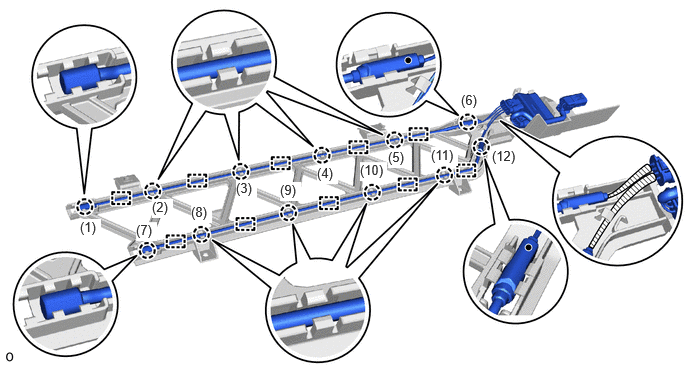

Detach the clamp.
- NOTICE:
- ·
Do not pull strongly on the wire.
·Do not twist the wire.
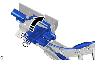
|
|
Remove in this Direction |
Detach the claw in the direction indicated by the arrow as shown in the illustration.
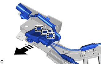
|
|
Remove in this Direction |
Detach the guide and remove the kick door control sensor from the kick door control bracket in the direction indicated by the arrow shown in the illustration.
- NOTICE:
- ·
Do not subject the kick door control sensor to strong impacts or force, and do not drop it.
·Do not reuse a kick door control sensor which has been subjected to an impact or dropped.