SUPPLEMENTAL RESTRAINT SYSTEMS AIRBAG SYSTEM(for GTMC Made) B000111 Driver Frontal Stage 1 Deployment Control Circuit Short to Ground
DESCRIPTION
| DTC No. | Detection Item | DTC Detection Condition | Trouble Area | Warning Indicate | Test Mode / Check Mode |
|---|---|---|---|---|---|
| B000111 | Driver Frontal Stage 1 Deployment Control Circuit Short to Ground | One of the following conditions is met:
·
The airbag ECU assembly detects a short circuit to ground signal in the driver side squib circuit for 0.5 seconds. ·
A spiral cable sub-assembly malfunction. ·
A horn button assembly malfunction. ·
An airbag ECU assembly malfunction. |
·
Wire harness ·
Spiral cable sub-assembly ·
Horn button assembly ·
Airbag ECU assembly |
Comes on | Applicable |
WIRING DIAGRAM
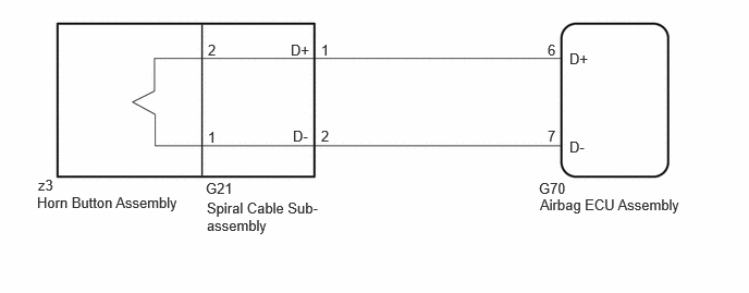
CAUTION / NOTICE / HINT
- NOTICE:
- ·
When installing the spiral cable sub-assembly and steering wheel, be sure to adjust the spiral cable sub-assembly as it may break if the steering wheel is turned before adjusting the spiral cable sub-assembly.
·After the ignition switch is turned off, there may be a waiting time before disconnecting the negative (-) auxiliary battery terminal.
·When disconnecting and reconnecting the auxiliary battery
- HINT:
-
When disconnecting and reconnecting the auxiliary battery, there is an automatic learning function that completes learning when the respective system is used.
·After replacing the airbag ECU assembly, refer to initialization.
- HINT:
-
To perform the simulation method, enter check mode (signal check) with the GTS (Vehicle Interior>SUPPLEMENTAL RESTRAINT SYSTEMS>AIRBAG SYSTEM (for GTMC Made)>CHECK MODE PROCEDURE202405,999999,_58,_083100,_0694959,RM100000002LV1D,), and then wiggle each connector of the airbag system or drive the vehicle on various types of road (General>INTRODUCTION>HOW TO TROUBLESHOOT ECU CONTROLLED SYSTEMS>HOW TO PROCEED WITH TROUBLESHOOTING201910,999999,_V1,_083040,_0402301,RM100000001JHCA,).
PROCEDURE
Turn the ignition switch to ON, and wait for at least 60 seconds.
Check for DTCs.
- Body Electrical > SRS Airbag > Trouble Codes
- 50001 444
- Result:
Proceed to DTC B000111 is output Past DTC B000111 is output
DTC B000111 is output
Past DTC B000111 is output
- HINT:
- ·
To perform the simulation method, enter check mode (signal check) with the GTS
·Perform the simulation method while checking the Data List.
Turn the ignition switch off.
Disconnect the cable from the negative (-) auxiliary battery terminal, and wait for at least 60 seconds.
Check that the connectors are properly connected to the horn button assembly, spiral cable sub-assembly and airbag ECU assembly.
- OK:
The connectors are properly connected.
- Result:
Proceed to OK NG
OK
NG
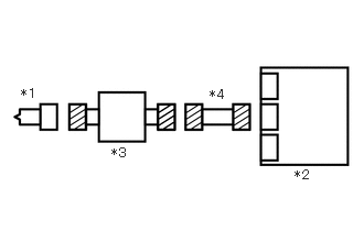
| *1 | Horn Button Assembly |
| *2 | Airbag ECU Assembly |
| *3 | Spiral Cable Sub-assembly |
| *4 | Wire Harness |
Disconnect the airbag ECU assembly connector.
Disconnect the spiral cable sub-assembly connector.
Disconnect the horn button assembly connector.
Check that the terminals of the connectors are not deformed or damaged.
- OK:
The terminals of the connectors are not deformed or damaged.
Check that the connectors are not loose, deformed or damaged.
- OK:
The connector locking button is not disengaged, and the claw of the lock is not deformed or damaged.
Check that the short springs of the activation prevention mechanisms of the wire harness connector are not deformed or damaged.
- OK:
The short springs are not deformed or damaged.
- Result:
Proceed to OK NG
OK
NG
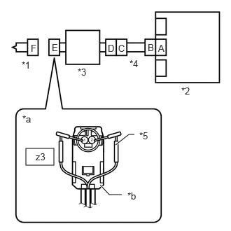
| *1 | Horn Button Assembly |
| *2 | Airbag ECU Assembly |
| *3 | Spiral Cable Sub-assembly |
| *4 | Wire Harness |
| *5 | SST |
| *a | Front view of wire harness connector
(to Horn Button Assembly) |
| *b | Color: Light Green |
Connect the G70 airbag ECU assembly connector.
Connect the G21 spiral cable sub-assembly connector.
Connect the white wire side of SST (resistance 2.1 Ω) to connector E (light green connector).
- CAUTION:
-
Never connect a tester to the horn button assembly for measurement, as this may lead to a serious injury due to airbag deployment.
- NOTICE:
- ·
Do not forcibly insert SST into the terminals of the connector when connecting it.
·Insert SST straight into the terminals of the connector.
- SST
- 09843-18061
Connect the cable to the negative (-) auxiliary battery terminal.
Turn the ignition switch to ON, and wait for at least 60 seconds.
Clear the DTCs stored in memory.
- Body Electrical > SRS Airbag > Clear DTCs
- 50002 444
Turn the ignition switch off.
Turn the ignition switch to ON, and wait for at least 60 seconds.
Check for DTCs.
- Body Electrical > SRS Airbag > Trouble Codes
- 50001 444
- Result:
Proceed to DTC B000111 is not output DTC B000111 is output
- HINT:
-
Codes other than DTC B000111 may be output at this time, but they are not related to this check.
Turn the ignition switch off.
Disconnect the cable from the negative (-) auxiliary battery terminal, and wait for at least 60 seconds.
Disconnect SST from connector E.
DTC B000111 is not output
DTC B000111 is output
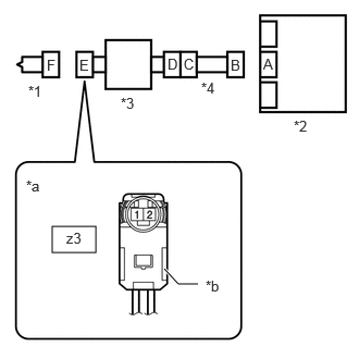
| *1 | Horn Button Assembly |
| *2 | Airbag ECU Assembly |
| *3 | Spiral Cable Sub-assembly |
| *4 | Wire Harness |
| *a | Front view of wire harness connector
(to Horn Button Assembly) |
| *b | Color: Light Green |
Disconnect the G70 airbag ECU assembly connector.
Measure the resistance according to the value(s) in the table below.
- Standard Resistance:
Tester Connection Condition Specified Condition z3-2 - Body ground Always 1 MΩ or higher z3-1 - Body ground Always 1 MΩ or higher
- Result:
Proceed to OK NG
OK
NG
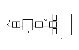
| *1 | Horn Button Assembly |
| *2 | Airbag ECU Assembly |
| *3 | Spiral Cable Sub-assembly |
| *4 | Wire Harness |
Connect the airbag ECU assembly connector.
Connect the horn button assembly connector.
Connect the cable to the negative (-) auxiliary battery terminal, and wait for at least 2 seconds.
Turn the ignition switch to ON, and wait for at least 60 seconds.
Clear the DTCs stored in memory.
- Body Electrical > SRS Airbag > Clear DTCs
- 50002 444
Turn the ignition switch off.
Turn the ignition switch to ON, and wait for at least 60 seconds.
Check for DTCs.
- Body Electrical > SRS Airbag > Trouble Codes
- 50001 444
- Result:
Proceed to DTC B000111 is not output DTC B000111 is output
- HINT:
-
Codes other than DTC B000111 may be output at this time, but they are not related to this check.
Turn the ignition switch off.
Disconnect the cable from the negative (-) auxiliary battery terminal, and wait for at least 60 seconds.
DTC B000111 is not output
- HINT:
- ·
To perform the simulation method, enter check mode (signal check) with the GTS
·Perform the simulation method while checking the Data List.
DTC B000111 is output
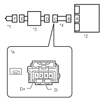
| *1 | Horn Button Assembly |
| *2 | Airbag ECU Assembly |
| *3 | Spiral Cable Sub-assembly |
| *4 | Wire Harness |
| *a | Front view of wire harness connector
(to Spiral Cable Sub-assembly) |
Disconnect the spiral cable sub-assembly connector.
Measure the resistance according to the value(s) in the table below.
- Standard Resistance:
Tester Connection Condition Specified Condition G21-1 (D+) - Body ground Always 1 MΩ or higher G21-2 (D-) - Body ground Always 1 MΩ or higher
- Result:
Proceed to OK NG
OK
NG