SUPPLEMENTAL RESTRAINT SYSTEMS SPIRAL CABLE INSTALLATION
CAUTION / NOTICE / HINT
- NOTICE:
- ·
After replacing the steering sensor, make sure to perform update ECU security key.
·After performing the update ECU security key procedure, make sure to perform the initialization procedure for when the cable has been disconnected and reconnected to the negative (-) auxiliary battery terminal.
PROCEDURE

 1.INSPECT SPIRAL CABLE SUB-ASSEMBLY
Check that the spiral cable sub-assembly is in the center position.
- OK:
The connector is at the top.
The alignment marks are aligned.
The colored roller or the top of the flat cable U-turn can be checked from the check window.
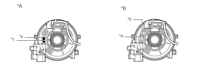
| *A | Colored Roller (Visible Type) | *B | Flat Cable (Visible Type) |
| *a | Check Window | *b | Alignment Mark |
| *c | Colored Roller | *d | Top of Flat Cable U-turn |
If the spiral cable sub-assembly is not centered, center it.
- NOTICE:
-
Failure to observe the following precautions may result in damage to the spiral cable sub-assembly.
- ·
When rotating the spiral cable sub-assembly, make sure to push on the interlock to release the interlock.
·Do not turn the spiral cable sub-assembly using the airbag wire harness.
·Do not forcibly rotate the part.
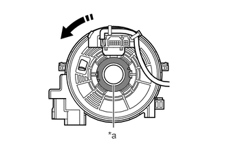
| *a | Interlock |

|
Counterclockwise |
While pushing on the interlock indicated in the illustration. Make sure to rotate the spiral cable sub-assembly counterclockwise slowly by hand until it stops.
- NOTICE:
-
Make sure to rotate the spiral cable sub-assembly counterclockwise. If rotated clockwise, it may be damaged or centering may no longer be possible.
- HINT:
-
The interlock operates at the top and bottom of the connector.
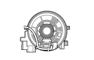
If the spiral cable sub-assembly stops rotating and the connector has moved past the bottom, return the connector to the bottom as shown in the illustration.
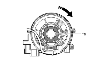
| *a | Interlock |
|
|
Clockwise |
While pushing on the interlock, rotate the spiral cable sub-assembly clockwise approximately 2.5 times to move the connector from the bottom to the top.
- NOTICE:
-
If the connector is rotated clockwise from the bottom 5 times or more, the spiral cable sub-assembly may be damaged.
- HINT:
-
The interlock operates at the top and bottom of the connector.
Check that the spiral cable sub-assembly is in the center position.
- OK:
The connector is at the top.
The alignment marks are aligned.
The colored roller or the top of the flat cable U-turn can be checked from the check window.
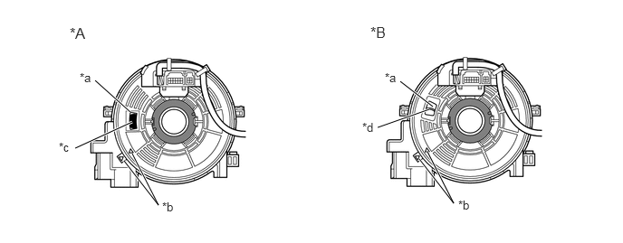
| *A | Colored Roller (Visible Type) | *B | Flat Cable (Visible Type) |
| *a | Check Window | *b | Alignment Mark |
| *c | Colored Roller | *d | Top of Flat Cable U-turn |
- NOTICE:
-
If the spiral cable sub-assembly cannot be centered, it is possible that the spiral cable sub-assembly is broken. Replace the spiral cable sub-assembly with a new one.
2.INSTALL STEERING SENSOR
- HINT:
-
Perform this procedure only when replacement of the spiral cable sub-assembly is necessary.
Install the steering sensor to a new spiral cable sub-assembly.
3.PLACE FRONT WHEELS FACING STRAIGHT AHEAD
4.INSTALL SPIRAL CABLE WITH SENSOR SUB-ASSEMBLY
- NOTICE:
- ·
Do not replace the spiral cable with sensor sub-assembly with the auxiliary battery connected and the ignition switch ON.
·Do not rotate the spiral cable with sensor sub-assembly with the auxiliary battery connected and the ignition switch ON.
·When rotating the spiral cable with sensor sub-assembly to check the operation of the spiral cable with sensor sub-assembly (checking for abnormal noise, checking the DTC, Data list, etc.) make sure to perform the inspection with the steering wheel assembly installed.
Check that the ignition switch is off.
Check that the cable is disconnected from the negative (-) auxiliary battery terminal.
- CAUTION:
- ·
Wait at least 60 seconds after disconnecting the cable from the negative (-) auxiliary battery terminal to disable the SRS system.
·If the airbag deploys for any reason, it may cause a serious accident.
Check that the front wheels are facing straight ahead.
Set the turn signal switch to the neutral position.
- NOTICE:
-
If it is not in the neutral position, the turn signal switch cancel ratchet may snap.
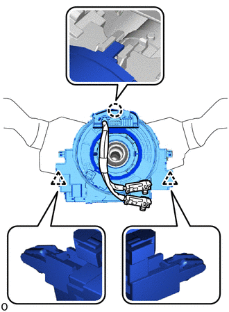
Attach the claw and clip to install the spiral cable with sensor sub-assembly.
Connect each connector.
- NOTICE:
-
When connecting any airbag connector, take care not to damage the airbag wire harness.
- HINT:
-
Refer to How to Connect or Disconnect Airbag Connector:
- ·
45286B
5.INSTALL UPPER STEERING COLUMN COVER
45287
6.INSTALL LOWER STEERING COLUMN COVER
7.ADJUST SPIRAL CABLE SUB-ASSEMBLY
Check that the ignition switch is off.
Check that the cable is disconnected from the negative (-) auxiliary battery terminal.
- CAUTION:
- ·
Wait at least 60 seconds after disconnecting the cable from the negative (-) auxiliary battery terminal to disable the SRS system.
·If the airbag deploys for any reason, it may cause a serious accident.
Check that the spiral cable sub-assembly is in the center position.
- OK:
The connector is at the top.
The colored roller or the top of the flat cable U-turn can be checked from the check window.
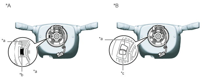
| *A | Colored Roller (Visible Type) | *B | Flat Cable (Visible Type) |
| *a | Check Window | *b | Colored Roller |
| *c | Top of Flat Cable U-turn | - | - |
If the spiral cable sub-assembly is not centered, center it.
- NOTICE:
-
Failure to observe the following precautions may result in damage to the spiral cable sub-assembly.
- ·
When rotating the spiral cable sub-assembly, make sure to push on the interlock to release the interlock.
·Do not turn the spiral cable sub-assembly using the airbag wire harness.
·Do not forcibly rotate the part.
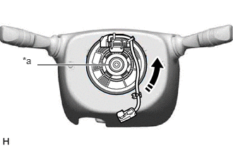
| *a | Interlock |
|
|
Counterclockwise |
While pushing on the interlock indicated in the illustration. Make sure to rotate the spiral cable sub-assembly counterclockwise slowly by hand until it stops.
- NOTICE:
-
If the connector is rotated clockwise from the bottom 5 times or more, the spiral cable sub-assembly may be damaged.
- HINT:
-
The interlock operates at the top and bottom of the connector.
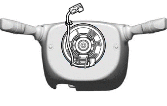
If the spiral cable sub-assembly stops rotating and the connector has moved past the bottom, return the connector to the bottom as shown in the illustration.
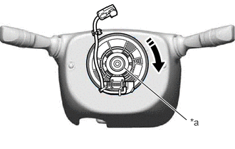
| *a | Interlock |
|
|
Clockwise |
While pushing on the interlock, rotate the spiral cable sub-assembly clockwise approximately 2.5 times to move the connector from the bottom to the top.
- NOTICE:
-
If the connector is rotated clockwise from the bottom 5 times or more, the spiral cable sub-assembly may be damaged.
- HINT:
-
The interlock operates at the top and bottom of the connector.
Check that the spiral cable sub-assembly is in the center position.
- OK:
The connector is at the top.
The colored roller or the top of the flat cable U-turn can be checked from the check window.
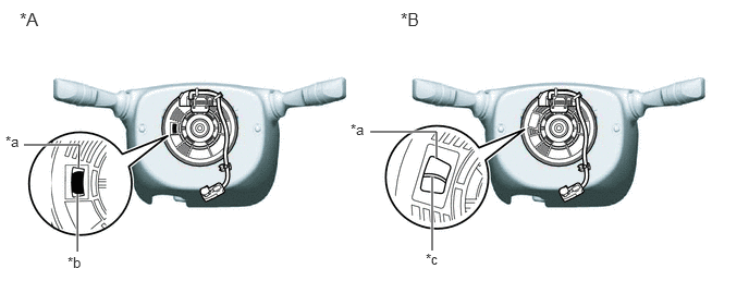
| *A | Colored Roller (Visible Type) | *B | Flat Cable (Visible Type) |
| *a | Check Window | *b | Colored Roller |
| *c | Top of Flat Cable U-turn | - | - |
- NOTICE:
-
If the spiral cable sub-assembly cannot be centered, it is possible that the spiral cable sub-assembly is broken. Replace the spiral cable sub-assembly with a new one.
45100
8.INSTALL STEERING WHEEL ASSEMBLY
9.CONNECT CABLE TO NEGATIVE AUXILIARY BATTERY TERMINAL
10. UPDATE ECU SECURITY KEY
11. INITIALIZATION AFTER RECONNECTING AUXILIARY BATTERY TERMINAL
- HINT:
-
When disconnecting and reconnecting the auxiliary battery, there is an automatic learning function that completes learning when the respective system is used.
12. PERFORM DIAGNOSTIC SYSTEM CHECK
13.CHECK SRS WARNING LIGHT