METER / GAUGE / DISPLAY METER / GAUGE SYSTEM(for SFTM Made) Speedometer Malfunction
DESCRIPTION
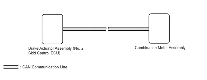
The combination meter assembly receives vehicle speed signals from the brake actuator assembly (No. 2 skid control ECU) via CAN communication. The speed sensor detects the wheel speed and sends the appropriate signals to the brake actuator assembly (No. 2 skid control ECU). The brake actuator assembly (No. 2 skid control ECU) supplies power to the vehicle speed sensor. The brake actuator assembly (No. 2 skid control ECU) detects vehicle speed signals based on pulses of the voltage.
- HINT:
- ·
Factors that affect the indicated vehicle speed include the tire size, tire inflation, and tire wear. The speed indicated on the speedometer has an allowable margin of error. This can be tested using the GTS. For details about testing and the margin of error, see the reference chart.
·If the vehicle speed sensor circuit has a malfunction, the brake actuator assembly (No. 2 skid control ECU) stores DTCs. Troubleshoot the electronically controlled brake system.
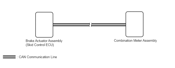
The combination meter assembly receives vehicle speed signals from the brake actuator assembly (skid control ECU) via CAN communication. The speed sensor detects the wheel speed and sends the appropriate signals to the brake actuator assembly (skid control ECU). The brake actuator assembly (skid control ECU) supplies power to the vehicle speed sensor. The brake actuator assembly (skid control ECU) detects vehicle speed signals based on pulses of the voltage.
- HINT:
- ·
Factors that affect the indicated vehicle speed include the tire size, tire inflation, and tire wear. The speed indicated on the speedometer has an allowable margin of error. This can be tested using the GTS. For details about testing and the margin of error, see the reference chart.
·If the vehicle speed sensor circuit has a malfunction, the brake actuator assembly (skid control ECU) stores DTCs. Troubleshoot the electronically controlled brake system.
WIRING DIAGRAM
CAUTION / NOTICE / HINT
- NOTICE:
- ·
If the vehicle speed is outside the allowable range when tested, perform the on-vehicle inspection.
·When replacing the combination meter assembly, always replace it with a new one. If a combination meter assembly which was installed to another vehicle is used, the information stored in it will not match the information from the vehicle and a DTC may be stored.
- HINT:
-
Before starting the following inspection, check tire size and tire air pressure.
PROCEDURE
Check if CAN communication DTCs are output.
for HV Model:
for Gasoline Model:
- Result:
Result Proceed to CAN communication DTCs are not output. (for HV Model) A CAN communication DTCs are not output. (for Gasoline Model) B CAN communication DTCs are output. C
A
B
C
for HV Model:
for Gasoline Model:
Check for DTCs.
- Chassis > Brake/EPB > Trouble Codes
- 50001 435
- Result:
Result Proceed to Electronically controlled brake system DTCs are not output. A Electronically controlled brake system DTC is output. B
A
B
Using the GTS, read the Data List.
- Body Electrical > Combination Meter > Data List
-
Tester Display Measurement Item Range Normal Condition Diagnostic Note Vehicle Speed Meter Vehicle speed Min.: 0 km/h (0 mph), Max.: 255 km/h (158 mph) Almost same as actual vehicle speed -
- Body Electrical > Combination Meter > Data List
-
Tester Display Vehicle Speed Meter - 50003 409 23
- HINT:
- ·
When the Data List values of the ECUs match, an internal malfunction of the combination meter assembly is suspected.
·When the Data List values of the ECUs do not match, a signal output error of the brake actuator assembly (No. 2 skid control ECU) or an internal malfunction of the combination meter assembly is suspected.
- OK:
Vehicle speed displayed on the GTS is almost the same as the actual vehicle speed measured using a speedometer tester (calibrated chassis dynamometer).
- Result:
Proceed to OK NG
OK
NG
Using the GTS, read the Data List.
- Chassis > Brake/EPB > Data List
-
Tester Display Measurement Item Range Normal Condition Diagnostic Note Vehicle Speed Vehicle speed
(Vehicle speed signal output to combination meter assembly)Min.: 0 km/h (0 mph), Max.: 6553.5 km/h (4072.34 mph) Almost same as actual vehicle speed
Vehicle stopped: 0 km/h (0 mph)When driving at constant speed: No large fluctuations
- Chassis > Brake/EPB > Data List
-
Tester Display Vehicle Speed - 50003 435 36
- OK:
Vehicle speed displayed on the GTS is almost the same as the actual vehicle speed measured using a speedometer tester (calibrated chassis dynamometer).
- Result:
Proceed to OK NG
OK
NG
Check for DTCs.
- Chassis > Brake/EPB > Trouble Codes
- 50001 435
- Result:
Result Proceed to Electronically controlled brake system DTCs are not output. A Electronically controlled brake system DTC is output. B
A
B
Using the GTS, read the Data List.
- Body Electrical > Combination Meter > Data List
-
Tester Display Measurement Item Range Normal Condition Diagnostic Note Vehicle Speed Meter Vehicle speed Min.: 0 km/h (0 mph), Max.: 255 km/h (158 mph) Almost same as actual vehicle speed -
- Body Electrical > Combination Meter > Data List
-
Tester Display Vehicle Speed Meter - 50003 409 23
- HINT:
- ·
When the Data List values of the ECUs match, an internal malfunction of the combination meter assembly is suspected.
·When the Data List values of the ECUs do not match, a signal output error of the brake actuator assembly (skid control ECU) or an internal malfunction of the combination meter assembly is suspected.
- OK:
Vehicle speed displayed on the GTS is almost the same as the actual vehicle speed measured using a speedometer tester (calibrated chassis dynamometer).
- Result:
Proceed to OK NG
OK
NG
Using the GTS, read the Data List.
- Chassis > Brake/EPB > Data List
-
Tester Display Measurement Item Range Normal Condition Diagnostic Note Vehicle Speed Vehicle speed
(Vehicle speed signal output to combination meter assembly)Min.: 0 km/h (0 mph), Max.: 6553.5 km/h (4072.34 mph) Almost same as actual vehicle speed
Vehicle stopped: 0 km/h (0 mph)When driving at constant speed: No large fluctuations
- Chassis > Brake/EPB > Data List
-
Tester Display Vehicle Speed - 50003 435 36
- OK:
Vehicle speed displayed on the GTS is almost the same as the actual vehicle speed measured using a speedometer tester (calibrated chassis dynamometer).
- Result:
Proceed to OK NG
OK
NG