METER / GAUGE / DISPLAY METER / GAUGE SYSTEM(for SFTM Made) B150819 Turn Signal/Hazard Flasher Circuit Current Above Threshold
DESCRIPTION
| DTC No. | Detection Item | DTC Detection Condition | Trouble Area |
|---|---|---|---|
| B150819 | Turn Signal/Hazard Flasher Circuit Current Above Threshold | Diagnosis Condition:
Auxiliary battery voltage is 10 V or more Malfunction Status:
·
Short in front turn signal light circuit ·
Short in side turn signal light circuit ·
Short in rear turn signal light circuit |
·
Harness or connector ·
Headlight unit assembly ·
Headlight assembly*1 ·
Headlight front turn signal LED*2 ·
Outer rear view mirror assembly ·
Side turn signal light assembly ·
Rear combination light socket and wire ·
Combination meter assembly |
*1: for Triple Beam Headlight
*2: for Single Beam Headlight
WIRING DIAGRAM
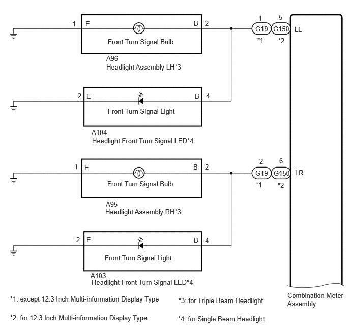
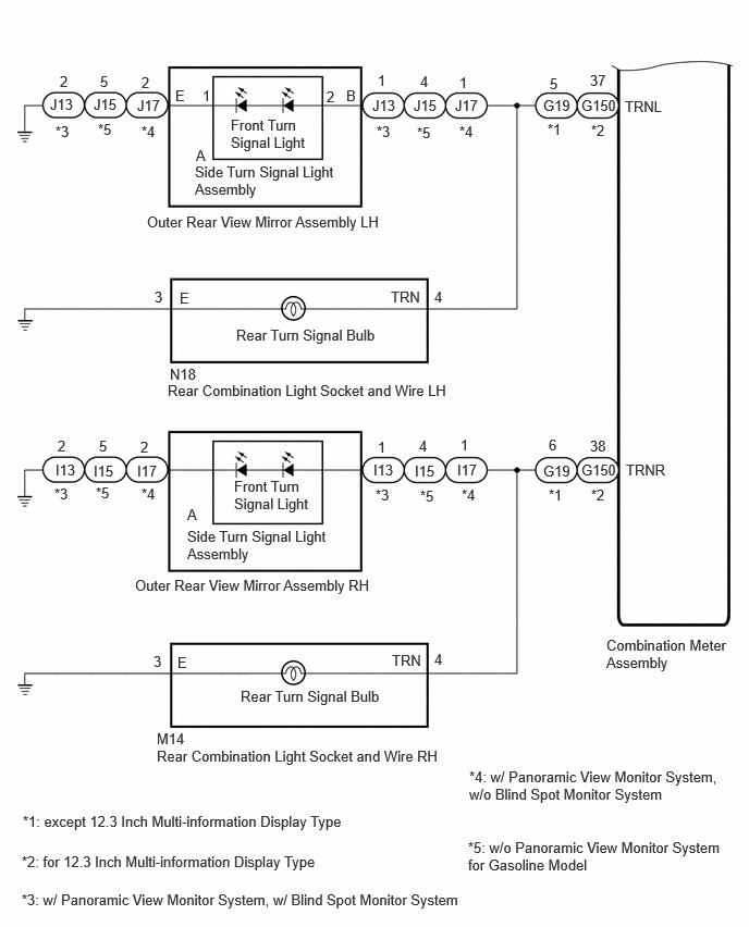
CAUTION / NOTICE / HINT
- NOTICE:
- ·
When replacing the combination meter assembly, always replace it with a new one. If a combination meter assembly which was installed to another vehicle is used, the information stored in it will not match the information from the vehicle and a DTC may be stored.
·Bulb Type Turn Light:
Inspect the bulbs before performing the following procedure.
PROCEDURE
Inspect the illumination of each turn signal light.
- Result:
Result Proceed to Front turn signal light LH does not blink. A Front turn signal light RH does not blink. B Rear turn signal light LH and side turn signal light LH do not blink. C Rear turn signal light RH and side turn signal light RH do not blink. D
A
B
C
D
Check vehicle condition.
- Result:
Result Proceed to for Triple Beam Headlight A for Single Beam Headlight B
A
B
Disconnect the A96 headlight assembly LH connector.
Clear the DTCs.
- Body Electrical > Combination Meter > Clear DTCs
- 50002 409
Check for DTCs.
- Body Electrical > Combination Meter > Trouble Codes
- 50001 409
- Result:
Result Proceed to DTC B150819 is output. A DTC B150718 is output. B
A
B
*1: except 12.3 Inch Multi-information Display Type
*2: for 12.3 Inch Multi-information Display Type
*3: for Triple Beam Headlight
*4: for Single Beam Headlight
Disconnect the G19*1 or G150*2 combination meter assembly connector.
Disconnect the A96 headlight assembly LH connector.*3
Disconnect the A104 headlight front turn signal LED connector.*4
Measure the resistance according to the value(s) in the table below.
- Standard Resistance:
for Triple Beam Headlight Tester Connection Condition Specified Condition G19-1 (LL)*1 or G150-5 (LL)*2 or A96-2 (B) - Body ground Always 10 kΩ or higher
for Single Beam Headlight Tester Connection Condition Specified Condition G19-1 (LL)*1 or G150-5 (LL)*2 or A104-4 (B) - Body ground Always 10 kΩ or higher
- Result:
Proceed to OK NG
OK
NG
Disconnect the A104 headlight front turn signal LED connector.
Clear the DTCs.
- Body Electrical > Combination Meter > Clear DTCs
- 50002 409
Check for DTCs.
- Body Electrical > Combination Meter > Trouble Codes
- 50001 409
- Result:
Result Proceed to DTC B150819 is output. A DTC B150718 is output. B
A
B
Check vehicle condition.
- Result:
Result Proceed to for Triple Beam Headlight A for Single Beam Headlight B
A
B
Disconnect the A95 headlight assembly RH connector.
Clear the DTCs.
- Body Electrical > Combination Meter > Clear DTCs
- 50002 409
Check for DTCs.
- Body Electrical > Combination Meter > Trouble Codes
- 50001 409
- Result:
Result Proceed to DTC B150819 is output. A DTC B150718 is output. B
A
B
*1: except 12.3 Inch Multi-information Display Type
*2: for 12.3 Inch Multi-information Display Type
*3: for Triple Beam Headlight
*4: for Single Beam Headlight
Disconnect the G19*1 or G150*2 combination meter assembly connector.
Disconnect the A95 headlight assembly RH connector.*3
Disconnect the A103 headlight front turn signal LED connector.*4
Measure the resistance according to the value(s) in the table below.
- Standard Resistance:
for Triple Beam Headlight Tester Connection Condition Specified Condition G19-2 (LR)*1 or G150-6 (LR)*2 or A95-2 (B) - Body ground Always 10 kΩ or higher
for Single Beam Headlight Tester Connection Condition Specified Condition G19-2 (LR)*1 or G150-6 (LR)*2 or A103-4 (B) - Body ground Always 10 kΩ or higher
- Result:
Proceed to OK NG
OK
NG
Disconnect the A103 headlight front turn signal LED connector.
Clear the DTCs.
- Body Electrical > Combination Meter > Clear DTCs
- 50002 409
Check for DTCs.
- Body Electrical > Combination Meter > Trouble Codes
- 50001 409
- Result:
Result Proceed to DTC B150819 is output. A DTC B150718 is output. B
A
B
Disconnect the J13*1, J15*3*4 or J17*2 outer rear view mirror assembly LH connector.
*1: w/ Panoramic View Monitor System, w/ Blind Spot Monitor System
*2: w/ Panoramic View Monitor System, w/o Blind Spot Monitor System
*3: w/o Panoramic View Monitor System
*4: for Gasoline Model
Clear the DTCs.
- Body Electrical > Combination Meter > Clear DTCs
- 50002 409
Check for DTCs.
- Body Electrical > Combination Meter > Trouble Codes
- 50001 409
- Result:
Result Proceed to DTC B150819 is output. A DTC B150718 is output. B
A
B
Disconnect the N18 rear combination light socket and wire LH connector.
Clear the DTCs.
- Body Electrical > Combination Meter > Clear DTCs
- 50002 409
Check for DTCs.
- Body Electrical > Combination Meter > Trouble Codes
- 50001 409
- Result:
Result Proceed to DTC B150819 is output. A DTC B150718 is output. B
A
B
*1: w/ Panoramic View Monitor System, w/ Blind Spot Monitor System
*2: w/ Panoramic View Monitor System, w/o Blind Spot Monitor System
*3: w/o Panoramic View Monitor System
*4: except 12.3 Inch Multi-information Display Type
*5: for 12.3 Inch Multi-information Display Type
*6: for Gasoline Model
*7: w/ Panoramic View Monitor System
Disconnect the G19*4 or G150*5 combination meter assembly connector.
Disconnect the N18 rear combination light socket and wire LH connector.
Disconnect the J13*1, J15*3*6 or J17*2 outer rear view mirror assembly LH connector.
Measure the resistance according to the value(s) in the table below.
- Standard Resistance:
except 12.3 Inch Multi-information Display Type Tester Connection Condition Specified Condition G19-5 (TRNL) or N18-4 (TRN) or J15-4 (B)*3*6 or J17-1 (B)*2 - Body ground Always 10 kΩ or higher
for 12.3 Inch Multi-information Display Type Tester Connection Condition Specified Condition G150-37 (TRNL) or N18-4 (TRN) or J13-1 (B)*1 or J17-1 (B)*2 - Body ground Always 10 kΩ or higher
- Result:
Proceed to OK NG
OK
NG
Remove the side turn signal light assembly LH.
Reconnect the J13*1, J15*3*4 or J17*2 outer rear view mirror assembly LH connector.
*1: w/ Panoramic View Monitor System, w/ Blind Spot Monitor System
*2: w/ Panoramic View Monitor System, w/o Blind Spot Monitor System
*3: w/o Panoramic View Monitor System
*4: for Gasoline Model
Clear the DTCs.
- Body Electrical > Combination Meter > Clear DTCs
- 50002 409
Check for DTCs.
- Body Electrical > Combination Meter > Trouble Codes
- 50001 409
- Result:
Result Proceed to DTC B150819 is output. A DTC B150718 is output. B
A
B
Disconnect the I13*1, I15*3*4 or I17*2 outer rear view mirror assembly RH connector.
*1: w/ Panoramic View Monitor System, w/ Blind Spot Monitor System
*2: w/ Panoramic View Monitor System, w/o Blind Spot Monitor System
*3: w/o Panoramic View Monitor System
*4: for Gasoline Model
Clear the DTCs.
- Body Electrical > Combination Meter > Clear DTCs
- 50002 409
Check for DTCs.
- Body Electrical > Combination Meter > Trouble Codes
- 50001 409
- Result:
Result Proceed to DTC B150819 is output. A DTC B150718 is output. B
A
B
Disconnect the M14 rear combination light socket and wire RH connector.
Clear the DTCs.
- Body Electrical > Combination Meter > Clear DTCs
- 50002 409
Check for DTCs.
- Body Electrical > Combination Meter > Trouble Codes
- 50001 409
- Result:
Result Proceed to DTC B150819 is output. A DTC B150718 is output. B
A
B
*1: w/ Panoramic View Monitor System, w/ Blind Spot Monitor System
*2: w/ Panoramic View Monitor System, w/o Blind Spot Monitor System
*3: w/o Panoramic View Monitor System
*4: except 12.3 Inch Multi-information Display Type
*5: for 12.3 Inch Multi-information Display Type
*6: for Gasoline Model
*7: w/ Panoramic View Monitor System
Disconnect the G19*4 or G150*5 combination meter assembly connector.
Disconnect the M14 rear combination light socket and wire RH connector.
Disconnect the I13*1, I15*3*6 or I17*2 outer rear view mirror assembly RH connector.
Measure the resistance according to the value(s) in the table below.
- Standard Resistance:
except 12.3 Inch Multi-information Display Type Tester Connection Condition Specified Condition G19-6 (TRNR) or M14-4 (TRN) or I15-4 (B)*3*6 or I17-1 (B)*2 - Body ground Always 10 kΩ or higher
for 12.3 Inch Multi-information Display Type Tester Connection Condition Specified Condition G150-38 (TRNR) or M14-4 (TRN) or I13-1 (B)*1 or I17-1 (B)*2 - Body ground Always 10 kΩ or higher
- Result:
Proceed to OK NG
OK
NG
Remove the side turn signal light assembly RH.
Reconnect the I13*1, I15*3*4 or I17*2 outer rear view mirror assembly RH connector.
*1: w/ Panoramic View Monitor System, w/ Blind Spot Monitor System
*2: w/ Panoramic View Monitor System, w/o Blind Spot Monitor System
*3: w/o Panoramic View Monitor System
*4: for Gasoline Model
Clear the DTCs.
- Body Electrical > Combination Meter > Clear DTCs
- 50002 409
Check for DTCs.
- Body Electrical > Combination Meter > Trouble Codes
- 50001 409
- Result:
Result Proceed to DTC B150819 is output. A DTC B150718 is output. B
A
B