DRIVE SHAFT / PROPELLER SHAFT REAR DRIVE SHAFT ASSEMBLY REASSEMBLY
CAUTION / NOTICE / HINT
- NOTICE:
- ·
When using a vise, place aluminum plates between the part and vise.
·When using a vise, do not overtighten it.
- HINT:
- ·
Use the same procedure for the RH and LH sides.
·The procedure listed below is for the LH side.
·Refer to the illustration to confirm the type of drive shaft assembly.
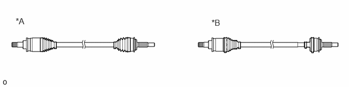 0.323,0.333 0.698,0.573 0.375,0.24 12 false *A 4.344,0.365 4.719,0.604 0.375,0.24 12 false *B
*A for Type A *B for Type B
PROCEDURE

 1.INSTALL OUTBOARD JOINT BOOT (for Type A)
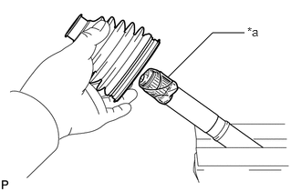
| *a | Protective Tape |
Wrap the splines of the rear drive shaft outboard joint shaft assembly with protective tape to prevent the boot from being damaged.
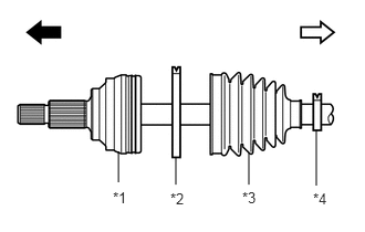
| *1 | Rear Drive Outboard Joint Shaft Assembly |
| *2 | Rear No. 2 Drive Shaft Outboard Joint Boot Clamp |
| *3 | Rear Drive Shaft Outboard Joint Boot |
| *4 | Rear Drive Shaft Outboard Joint Boot Clamp |

|
Outboard Joint Side |

|
Inboard Joint Side |
Install new parts to the rear drive shaft outboard joint shaft assembly in the following order:
Rear No. 2 drive shaft outboard joint boot clamp
Rear drive shaft outboard joint boot
Rear drive shaft outboard joint boot clamp
Pack the joint portion of the rear drive shaft outboard joint shaft assembly and outboard joint boot with grease.
- Standard Grease Capacity:
45.0 to 65.0 g (1.59 to 2.29 oz)
Install the rear drive shaft outboard joint boot to the rear drive shaft outboard joint shaft assembly groove.
- NOTICE:
- ·
Do not allow grease to adhere to the boot clamp track of the rear drive shaft outboard joint boot.
·Keep the inside of the rear drive shaft outboard joint boot free of foreign matter.
2.INSTALL OUTBOARD JOINT BOOT (for Type B)
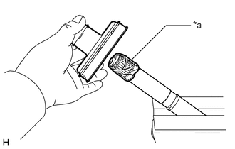
| *a | Protective Tape |
Wrap the splines of the rear drive shaft outboard joint shaft assembly with protective tape to prevent the boot from being damaged.
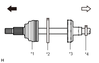
| *1 | Rear Drive Shaft Outboard Joint Shaft Assembly |
| *2 | Rear No. 2 Drive Shaft Outboard Joint Boot Clamp |
| *3 | Rear Drive Shaft Outboard Joint Boot |
| *4 | Rear Drive Shaft Outboard Joint Boot Clamp |
|
|
Outboard Joint Side |
|
|
Inboard Joint Side |
Install new parts to the rear drive shaft outboard joint shaft assembly in the following order:
Rear No. 2 drive shaft outboard joint boot clamp
Rear drive shaft outboard joint boot
Rear drive shaft outboard joint boot clamp
Pack the joint portion of the rear drive shaft outboard joint shaft assembly and rear drive shaft outboard joint boot with grease.
- Standard Grease Capacity:
30 to 35 g (1.06 to 1.23 oz)
Install the rear drive shaft outboard joint boot to the rear drive shaft outboard joint shaft assembly groove.
- NOTICE:
- ·
Do not allow grease to adhere to the boot clamp track of the outboard joint boot.
·Keep the inside of the outboard joint boot free of foreign matter.
42346F
3.INSTALL REAR NO. 2 DRIVE SHAFT OUTBOARD JOINT BOOT CLAMP LH (for Type A)
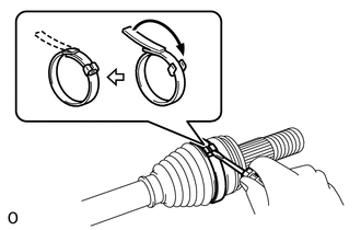
Using a screwdriver, install the rear No. 2 drive shaft outboard joint boot clamp LH as shown in the illustration.
- NOTICE:
-
Be careful not to damage the outboard joint boot.
42346F
4.INSTALL REAR NO. 2 DRIVE SHAFT OUTBOARD JOINT BOOT CLAMP LH (for Type B)
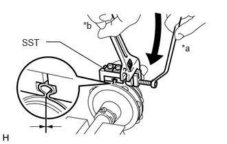
| *a | Turn |
| *b | Hold |
Install SST to the rear No. 2 drive shaft outboard joint boot clamp LH, and then while pressing the outboard joint boot, slightly tighten the SST bolt.
- SST
- 09521-24010
- NOTICE:
- ·
Correctly set the rear No. 2 drive shaft outboard joint boot clamp LH to the guide groove.
·Do not damage the outboard joint boot.
Tighten SST so that the rear No. 2 drive shaft outboard joint boot clamp is pinched.
- Clearance:
2.8 to 3.6 mm (0.111 to 0.141 in.)
- NOTICE:
- ·
When tightening SST, make sure the clearance of the rear No. 2 drive shaft inboard joint boot clamp LH is within the standard clearance.
·Do not damage the outboard joint boot.
Remove SST from the rear No. 2 drive shaft outboard joint boot clamp LH.
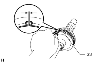
Using SST, measure the clearance of the rear No. 2 drive shaft outboard joint boot clamp.
- SST
- 09240-00021
- Clearance:
2.8 to 3.6 mm (0.111 to 0.141 in.)
- NOTICE:
-
If the measured value exceeds the specified value, retighten the rear drive shaft No. 2 axle inboard joint boot clamp.
42346D
5.INSTALL REAR DRIVE SHAFT OUTBOARD JOINT BOOT CLAMP LH (for Type A)
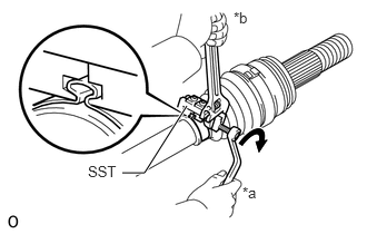
| *a | Turn |
| *b | Hold |
Install SST to the rear drive shaft ouboard joint boot clamp LH, and then while pressing the outboard joint boot, slightly tighten the SST bolt.
- SST
- 09521-24010
- NOTICE:
- ·
Correctly set the rear drive shaft outboard joint boot clamp LH to the guide groove.
·Do not damage the outboard joint boot.
Tighten SST so that the rear drive shaft outboard joint boot clamp LH is pinched.
- Clearance:
1.2 to 4.0 mm (0.048 to 0.157 in.)
- NOTICE:
- ·
When tightening SST, make sure the clearance of the rear drive shaft outboard joint boot clamp LH is within the standard clearance.
·Do not damage the outboard joint boot.
Remove SST from the rear 2 drive shaft outboard joint boot clamp LH.
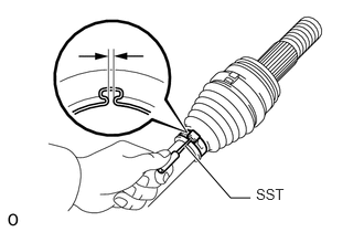
Using SST, measure the clearance of the rear drive shaft outboard joint boot clamp LH.
- SST
- 09240-00021
- Clearance:
1.2 to 4.0 mm (0.048 to 0.157 in.)
- NOTICE:
-
If the measured value exceeds the specified value, retighten the rear drive shaft outboard joint boot clamp LH.
42346D
6.INSTALL REAR DRIVE SHAFT OUTBOARD JOINT BOOT CLAMP LH (for Type B)
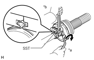
| *a | Turn |
| *b | Hold |
Install SST to the rear drive shaft outboard joint boot clamp LH, and then while pressing the outboard joint boot, slightly tighten the SST bolt.
- SST
- 09521-24010
- NOTICE:
- ·
Correctly set the rear drive shaft outboard joint boot clamp LH to the guide groove.
·Do not damage the outboard joint boot.
Tighten SST so that the rear drive shaft outboard joint boot clamp LH is pinched.
- Clearance:
2.8 to 3.6 mm (0.111 to 0.141 in.)
- NOTICE:
- ·
When tightening SST, make sure the clearance of the rear No. 2 drive shaft inboard joint boot clamp LH is within the standard clearance.
·Do not damage the outboard joint boot.
Remove SST from the rear drive shaft outboard joint boot clamp LH.
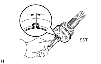
Using SST, measure the clearance of the rear drive shaft outboard joint boot clamp LH.
- SST
- 09240-00021
- Clearance:
2.8 to 3.6 mm (0.111 to 0.141 in.)
- NOTICE:
-
If the measured value exceeds the specified value, retighten the rear drive shaft outboard joint boot clamp.
42360D
7.INSTALL REAR DRIVE SHAFT INBOARD JOINT ASSEMBLY LH (for Type A)
Wrap the spline of the rear drive shaft outboard joint shaft assembly with protective tape to prevent the boot from being damaged.
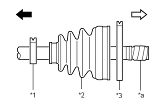
| *1 | Rear Drive Shaft Inboard Joint Boot Clamp LH |
| *2 | Rear Drive Shaft Inboard Joint Boot LH |
| *3 | Rear No. 2 Drive Shaft Inboard Joint Boot Clamp LH |
| *a | Protective Tape |
|
|
Outboard Joint Side |
|
|
Inboard Joint Side |
Install new parts to the rear drive outboard joint shaft assembly LH in the following order.
Rear drive shaft inboard joint boot clamp LH
Inboard joint boot
Rear No. 2 drive shaft inboard joint boot clamp LH
Remove the protective tape from the rear drive outboard joint shaft assembly LH.
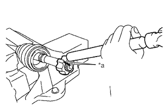
| *a | Matchmark |
Align the matchmarks placed before removal and install the inner race to the rear drive shaft outboard joint shaft assembly LH using a brass bar and a hammer.
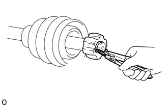
Using a snap ring expander, install a new snap ring.
- NOTICE:
-
The snap ring should be installed completely.
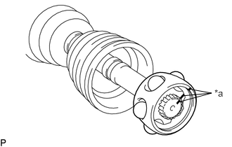
| *a | Matchmark |
Align the matchmarks placed before removal and install the ball cage to the inner race.
Install the 6 balls with grease to the inner race.
- NOTICE:
-
Do not drop the balls.
- HINT:
-
Apply grease onto the balls to keep them from falling.
Pack the rear drive shaft inboard joint assembly LH and inboard joint boot with grease from the boot kit.
- Standard Grease Capacity:
85.0 to 105.0 g (3.00 to 3.70 oz)

| *a | Matchmark |
Align the matchmarks and install the rear drive shaft inboard joint assembly LH to the rear drive outboard joint shaft assembly LH.
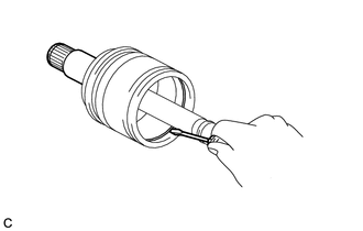
Using a screwdriver, install a new drive shaft snap ring to the rear drive shaft inboard joint assembly LH.
42360D
8.INSTALL REAR DRIVE SHAFT INBOARD JOINT ASSEMBLY LH (for Type B)
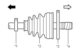
| *1 | Rear Drive Shaft Inboard Joint Boot Clamp |
| *2 | Rear Drive Shaft Inboard Joint Boot |
| *3 | Rear No. 2 Drive Shaft Inboard Joint Boot Clamp |
| *a | Protective Tape |
|
|
Outboard Joint Side |
|
|
Inboard Joint Side |
Install new parts to the rear drive shaft outboard joint shaft assembly in the following order:
Rear drive shaft inboard joint boot clamp
Rear drive shaft inboard joint boot
Rear No. 2 drive shaft inboard joint boot clamp
Secure the drive shaft in a vise between aluminum plates.
- NOTICE:
-
Do not overtighten the vise.
Remove the protective tape.
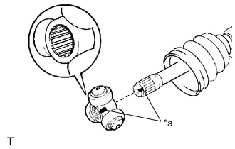
| *a | Matchmark |
Align the matchmarks and install the tripod joint to the rear drive shaft outboard joint shaft assembly.
- NOTICE:
-
Face the serrated side of the tripod joint outward and install it to the outboard joint end.
Using a brass bar and a hammer, install the tripod joint to the rear drive shaft outboard joint shaft assembly.
- NOTICE:
- ·
Do not tap the rollers.
·Keep the tripod joint free of foreign matter.
·Be sure to install the tripod joint in the correct direction.
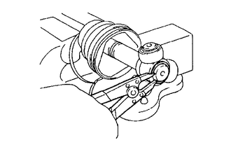
Using a snap ring expander, install a new shaft snap ring to the rear drive shaft outboard joint shaft assembly.
Pack the rear drive shaft inboard joint assembly and rear drive shaft inboard joint boot with grease.
- Standard Grease Capacity:
114 to 124 g (4.02 to 4.37 oz)
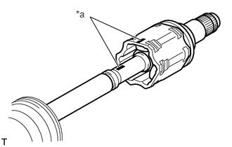
| *a | Matchmark |
Align the matchmarks and install the rear drive inboard joint assembly to the rear drive outboard joint shaft assembly.
9.INSTALL INBOARD JOINT BOOT (for Type A)
Install the inboard joint boot to the rear drive shaft inboard joint assembly.
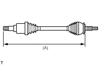
Check whether the drive shaft dimension (A) is within specification.
for Gasoline Model
- Length (A):
Item Length for Torque Vectoring Differential LH Side 626.4 mm (2.05 ft.) RH Side 611.4 mm (2.01 ft.) except Torque Vectoring Differential 755.3 mm (2.48 ft.)
for HV Model
- Length (A):
Item Length LH Side 718.4 mm (2.36 ft.) RH Side 791.4 mm (2.60 ft.)
- NOTICE:
-
Keep the drive shaft assembly level during inspection.
If the boots are stretched or contracted, correct them.
10.INSTALL INBOARD JOINT BOOT (for Type B)
Install the rear drive shaft inboard joint boot to the rear drive shaft inboard joint assembly.
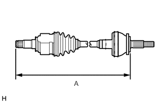
Check whether the drive shaft dimension (A) is within specification.
- Length (A):
Item Length LH Side 754.35 mm (2.47 ft.) RH Side 790.45 mm (2.59 ft.)
42347F
11.INSTALL REAR NO. 2 DRIVE SHAFT INBOARD JOINT BOOT CLAMP LH (for Type A)
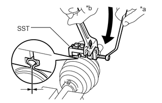
| *a | Turn |
| *b | Hold |
Install SST to the rear No. 2 drive shaft inboard joint boot clamp LH, and then while pressing the outboard joint boot, slightly tighten the SST bolt.
- SST
- 09521-24010
- NOTICE:
- ·
Correctly set the rear No. 2 drive shaft inboard joint boot clamp LH to the guide groove.
·Do not damage the outboard joint boot.
Tighten SST so that the rear No. 2 drive shaft inboard joint boot clamp LH is pinched.
- Standard clearance:
1.2 to 4.0 mm (0.047 to 0.157 in.)
- NOTICE:
- ·
When tightening SST, make sure the clearance of the rear No. 2 drive shaft inboard joint boot clamp LH is within the standard clearance.
·Do not damage the inboard joint boot.
Remove SST from the rear No. 2 drive shaft inboard joint boot clamp LH.
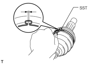
Using SST, measure the clearance of the rear drive shaft inboard joint boot clamp.
- SST
- 09240-00021
- Clearance:
1.2 to 4.0 mm (0.048 to 0.157 in.)
- NOTICE:
-
If the measured value exceeds the specified value, retighten the rear drive shaft No. 2 axle inboard joint boot clamp.
42347E
12.INSTALL REAR NO. 2 DRIVE SHAFT INBOARD JOINT BOOT CLAMP LH (for Type B)
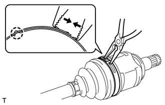
Using needle-nose pliers, install the rear No. 2 drive shaft inboard joint boot clamp LH as shown in the illustration.
- NOTICE:
-
Be careful not to damage the inboard joint boot.
42347D
13.INSTALL REAR DRIVE SHAFT INBOARD JOINT BOOT CLAMP LH (for Type A)
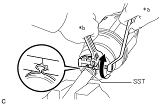
| *a | Turn |
| *b | Hold |
Install SST to the rear drive shaft inboard joint boot clamp LH, and then while pressing the inboard joint boot, slightly tighten the SST bolt.
- SST
- 09521-24010
- NOTICE:
- ·
Correctly set the rear drive shaft inboard joint boot clamp LH to the guide groove.
·Do not damage the outboard joint boot.
Tighten SST so that the rear drive shaft inboard joint boot clamp LH is pinched.
- NOTICE:
- ·
When tightening SST, make sure the clearance of the rear drive shaft inboard joint boot clamp LH is within the standard clearance.
·Do not damage the inboard joint boot.
Remove SST from the rear drive shaft inboard joint boot clamp LH.
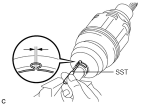
Using SST, measure the clearance of the rear drive shaft inboard joint boot clamp.
- SST
- 09240-00021
- Clearance:
1.2 to 4.0 mm (0.048 to 0.157 in.)
If the clearance is not as specified, retighten SST.
- NOTICE:
-
If the measured value exceeds the specified value, retighten the rear drive shaft inboard joint boot clamp LH.
42347D
14.INSTALL REAR DRIVE SHAFT INBOARD JOINT BOOT CLAMP LH (for Type B)
- HINT:
-
Use the same procedure described for the rear No. 2 drive shaft inboard joint boot clamp LH.
15.INSPECT REAR DRIVE SHAFT