SLIDING ROOF / CONVERTIBLE SLIDING ROOF SYSTEM(for Gasoline Model) B2341 Sensor (Motor) Failure B2344 Position Failure
DESCRIPTION
When the sliding roof ECU (sliding roof drive gear assembly) detects a motor malfunction and the sliding roof operation is stopped, DTC B2341 is stored.
When the sliding roof ECU (sliding roof drive gear assembly) detects a gear position malfunction and the sliding roof operation is stopped, DTC B2344 is stored.
| DTC No. | Detection Item | DTC Detection Condition | Trouble Area |
|---|---|---|---|
| B2341 | Sensor (Motor) Failure | Sensor (motor) failure (The sliding roof ECU (sliding roof drive gear assembly) enters fail-safe mode due to a problem with the motor) | ·
Sliding roof ECU (Sliding roof drive gear assembly) ·
Map light sub-assembly (slide/tilt switch) ·
Harness or connector |
| B2344 | Position Failure | Position failure (The sliding roof ECU (sliding roof drive gear assembly) enters fail-safe mode due to a problem with the gear position) | ·
Sliding roof ECU (Sliding roof drive gear assembly) ·
Map light sub-assembly (slide/tilt switch) ·
Harness or connector |
WIRING DIAGRAM
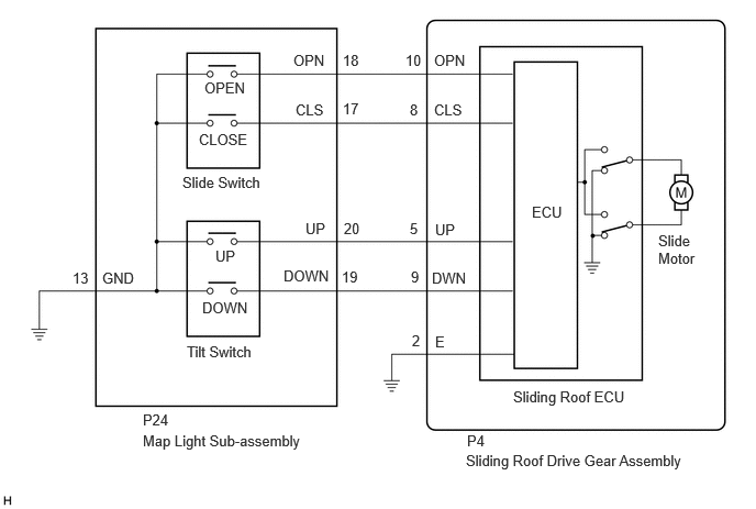
CAUTION / NOTICE / HINT
- NOTICE:
If the sliding roof ECU (sliding roof drive gear assembly) is removed and reinstalled or replaced, the sliding roof ECU (sliding roof drive gear assembly) must be initialized.
PROCEDURE
Check the sliding roof auto operation.
- OK:
Auto operation operates normally.
- Result:
Proceed to OK NG
OK
NG
Clear the DTCs.
- Body Electrical > Sliding Roof > Clear DTCs
- 50002 147
Check for DTCs.
- Body Electrical > Sliding Roof > Trouble Codes
- 50001 147
- OK:
DTCs B2341 or B2344 is not output.
- Result:
Proceed to OK NG
OK
NG
Check that the sliding roof ECU (sliding roof drive gear assembly) can be initialized.
- OK:
Sliding roof ECU (sliding roof drive gear assembly) can be initialized.
- Result:
Proceed to OK NG
OK
NG
Clear the DTCs.
- Body Electrical > Sliding Roof > Clear DTCs
- 50002 147
Check for DTCs.
- Body Electrical > Sliding Roof > Trouble Codes
- 50001 147
- OK:
DTCs B2341 or B2344 is not output.
- Result:
Proceed to OK NG
OK
NG
Perform the Active Test according to the display on the GTS.
- Body Electrical > Sliding Roof > Active Test
-
Tester Display Measurement Item Control Range Diagnostic Note Slide Roof Operate sliding roof motor OFF / Opn/Dwn / Clos/Up -
- Body Electrical > Sliding Roof > Active Test
-
Tester Display Slide Roof - 50004 147 1
- OK:
Slide roof is operated using GTS.
- Result:
Proceed to OK NG
OK
NG
Read the Data List according to the display on the GTS.
- Body Electrical > Sliding Roof > Data List
-
Tester Display Measurement Item Range Normal Condition Diagnostic Note Open Switch OPEN switch signal OFF or ON OFF: OPEN switch on the slide switch not pressed
ON: OPEN switch on the slide switch pressed- Close Switch CLOSE switch signal OFF or ON OFF: CLOSE switch on the slide switch not pressed
ON: CLOSE switch on the slide switch pressed- Up Switch UP switch signal OFF or ON OFF: UP switch not on the tilt switch pressed
ON: UP switch on the tilt switch pressed- Down Switch DOWN switch signal OFF or ON OFF: DOWN switch on the tilt switch not pressed
ON: DOWN switch on the tilt switch pressed-
- Body Electrical > Sliding Roof > Data List
-
Tester Display Open Switch Close Switch Up Switch Down Switch - 50003 147 1,4,7,10
- OK:
The GTS display changes according to the operation of each switch as shown in the table.
- Result:
Proceed to OK NG
OK
NG
Remove the map light sub-assembly (slide/tilt switch).
Inspect the map light sub-assembly (slide/tilt switch).
- Result:
Proceed to OK NG
OK
NG
Disconnect the P24 map light sub-assembly (slide/tilt switch) connector.
Disconnect the P4 sliding roof ECU (sliding roof drive gear assembly) connector.
Measure the resistance according to the value(s) in the table below.
- Standard Resistance:
Tester Connection Condition Specified Condition P4-5 (UP) - P24-20 (UP) Always Below 1 Ω P4-8 (CLS) - P24-17 (CLS) Always Below 1 Ω P4-9 (DWN) - P24-19 (DOWN) Always Below 1 Ω P4-10 (OPN) - P24-18 (OPN) Always Below 1 Ω P4-2 (E) - Body ground Always Below 1 Ω P24-13 (GND) - Body ground Always Below 1 Ω P4-5 (UP) or P24-20 (UP) - Body ground Always 10 kΩ or higher P4-8 (CLS) or P24-17 (CLS) - Body ground Always 10 kΩ or higher P4-9 (DWN) or P24-19 (DOWN) - Body ground Always 10 kΩ or higher P4-10 (OPN) or P24-18 (OPN) - Body ground Always 10 kΩ or higher
- Result:
Proceed to OK NG
OK
NG