TELEMATICS TELEMATICS TRANSCEIVER INSTALLATION
CAUTION / NOTICE / HINT
- HINT:
-
A bolt without a torque specification is shown in the standard bolt chart.
PROCEDURE

 86741A
1.INSTALL TELEPHONE TRANSCEIVER
86741A
1.INSTALL TELEPHONE TRANSCEIVER
86719B
2.INSTALL NO. 2 TELEPHONE BRACKET
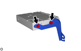
Install the No. 2 telephone bracket with the 2 screws.
- Torque:
- 3.0 N*m (31 kgf*cm, 27 in.*lbf)
86719A
3.INSTALL NO. 1 TELEPHONE BRACKET
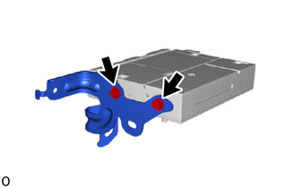
Install the No. 1 telephone bracket with the 2 screws.
- Torque:
- 3.0 N*m (31 kgf*cm, 27 in.*lbf)
86101Q
4.INSTALL NO. 4 ANTENNA CORD SUB-ASSEMBLY
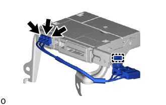
Attach the clamp to install the No. 4 antenna cord sub-assembly.
Connect the 3 connectors.
86713A
5.INSTALL TELEPHONE ECU WIRE (TO TRANSCEIVER)
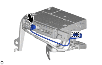
Connect the connector.
Attach the clamp to install the telephone ECU wire (to transceiver).
6.INSTALL TELEPHONE TRANSCEIVER WITH BRACKET
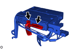
Connect the 2 connectors.
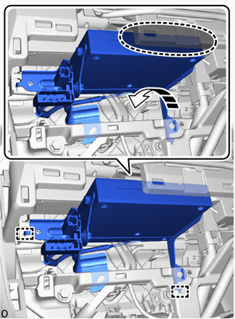

|
Place Hand Here |

|
Install in this Direction |
Place your hand at the position shown in the illustration, and then while bending the instrument panel safety pad assembly, attach the guide to temporarily install the telephone transceiver with bracket.
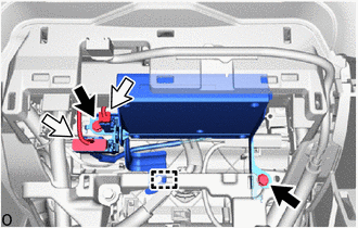

|
Bolt |

|
Connector |
Attach the clamp and connect the 2 connectors.
Install the telephone transceiver with bracket with the 2 bolts.
- Torque:
- 12 N*m (122 kgf*cm, 9 ft.*lbf)
55434B
7.INSTALL LOWER CENTER INSTRUMENT PANEL FINISH PANEL
55900
8.INSTALL AIR CONDITIONING CONTROL ASSEMBLY
58805C
9.INSTALL REAR UPPER CONSOLE PANEL SUB-ASSEMBLY
58813
10.INSTALL UPPER CONSOLE BOX (w/o Wireless Charger)
861C0
11.INSTALL MOBILE WIRELESS CHARGER CRADLE ASSEMBLY (w/ Wireless Charger)
58804A
12.INSTALL UPPER CONSOLE PANEL SUB-ASSEMBLY
33504F
13.INSTALL SHIFT LEVER KNOB SUB-ASSEMBLY
for Gasoline Model:
14.PERFORM REGISTRATION