DOOR / HATCH KICK SENSOR INSTALLATION
PROCEDURE

 891B2
1.INSTALL KICK DOOR CONTROL SENSOR (for Type A)
891B2
1.INSTALL KICK DOOR CONTROL SENSOR (for Type A)
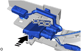

|
Install in this Direction |
Attach the guide in the direction indicated by the arrow shown in the illustration.
- NOTICE:
- ·
Do not subject the kick door control sensor to strong impacts or force, and do not drop it.
·Do not reuse a kick door control sensor which has been subjected to an impact or dropped.
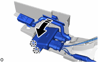
|
|
Install in this Direction |
Attach the claw and install the kick door control sensor in the direction indicated by the arrow as shown in the illustration.
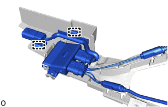
Attach the clamp.
- NOTICE:
- ·
Do not pull strongly on the wire.
·Do not twist the wire.
Attach the guide and claw in the order shown in the illustration and connect the antenna cable.
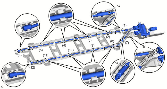
| *a | Paint Mark | *b | Tape (Red) |
- NOTICE:
- ·
Securely insert the antenna cable into the bracket until it reaches the bottom.
·Do not cross the red and black wires.
- HINT:
- ·
Install so that the paint mark is facing the top of the vehicle.
·Install the end of the antenna cable wrapped in tape to the rear side of the vehicle.
891B2
2.INSTALL KICK DOOR CONTROL SENSOR (for Type B)
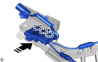
|
|
Install in this Direction |
Attach the guide in the direction indicated by the arrow shown in the illustration.
- NOTICE:
- ·
Do not subject the kick door control sensor to strong impacts or force, and do not drop it.
·Do not reuse a kick door control sensor which has been subjected to an impact or dropped.
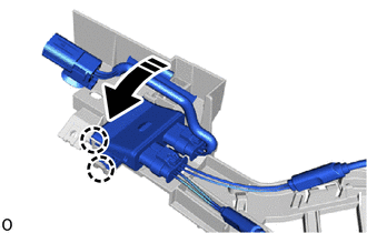
|
|
Install in this Direction |
Attach the claw and install the kick door control sensor in the direction indicated by the arrow as shown in the illustration.

Attach the clamp.
- NOTICE:
- ·
Do not pull strongly on the wire.
·Do not twist the wire.
Attach the guide and claw in the order shown in the illustration and connect the antenna cable.
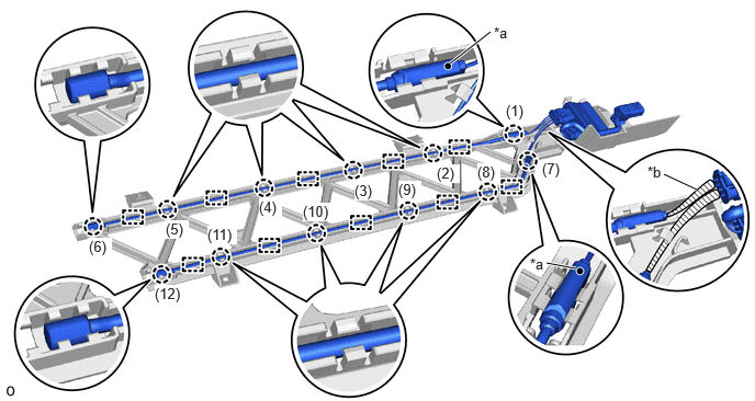
| *a | Paint Mark | *b | Tape (Red) |
- NOTICE:
- ·
Securely insert the antenna cable into the bracket until it reaches the bottom.
·Do not cross the red and black wires.
- HINT:
- ·
Install so that the paint mark is facing the top of the vehicle.
·Install the end of the antenna cable wrapped in tape to the rear side of the vehicle.
891B1
3.INSTALL KICK DOOR CONTROL BRACKET (for Type A)
Install the 2 clips in the order shown in the illustration and install the kick door control bracket together with the kick door control sensor.
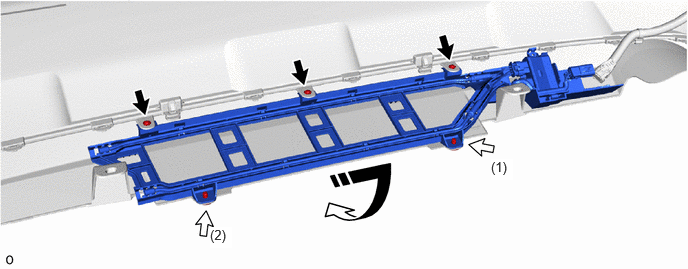
|
|
Install in this Direction | 
|
Screw |

|
Clip | - | - |
Install the 3 screws.
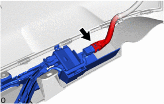
Connect the connector.
- NOTICE:
-
Do not touch the terminal of the kick door control sensor connector.
891B1
4.INSTALL KICK DOOR CONTROL BRACKET (for Type B)
Install the 2 clips in the order shown in the illustration and install the kick door control bracket together with the kick door control sensor.
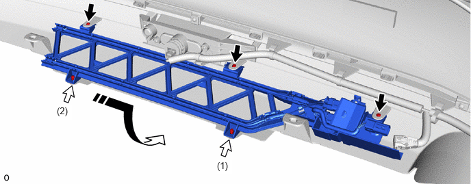
|
|
Install in this Direction |
|
Screw |
|
|
Clip | - | - |
Install the 3 screws.
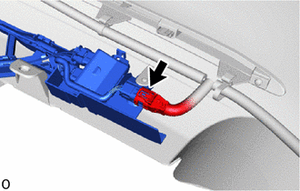
Connect the connector.
- NOTICE:
-
Do not touch the terminal of the kick door control sensor connector.
52159
5.INSTALL REAR BUMPER COVER
6.CONNECT CABLE TO NEGATIVE AUXILIARY BATTERY TERMINAL
7. INITIALIZATION AFTER RECONNECTING AUXILIARY BATTERY TERMINAL
- HINT:
-
When disconnecting and reconnecting the auxiliary battery, there is an automatic learning function that completes learning when the respective system is used.