PARK ASSIST / MONITORING PANORAMIC VIEW MONITOR SYSTEM SYSTEM DESCRIPTION
OPERATION EXPLANATION
The reverse position signal is sent from the shift position switch to the parking assist ECU when the shift position is moved to R.
An appropriate steering angle and timing information can be provided for the driver. This is based on the information from the steering angle sensor signal and the vehicle angle data signal that are sent to the parking assist ECU.
- HINT:
-
The steering angle sensor signal is used to control parking assist only for estimated guide line mode.
COMMUNICATION SYSTEM OUTLINE
CAN communication system
The panoramic view monitor system uses CAN communication for data communications between the parking assist ECU and each ECU.
If a problem occurs in the CAN communication line, the parking assist ECU outputs a CAN communication malfunction DTC. (To check, use the GTS.)
If a CAN communication line malfunction DTC is output, repair the malfunction in the communication line and troubleshoot the panoramic view monitor system when data communication is normal.
Since the CAN communication line has its own length and route, it cannot be repaired temporarily with a bypass wire, etc.
VIDEO SIGNALS
Video signal circuit
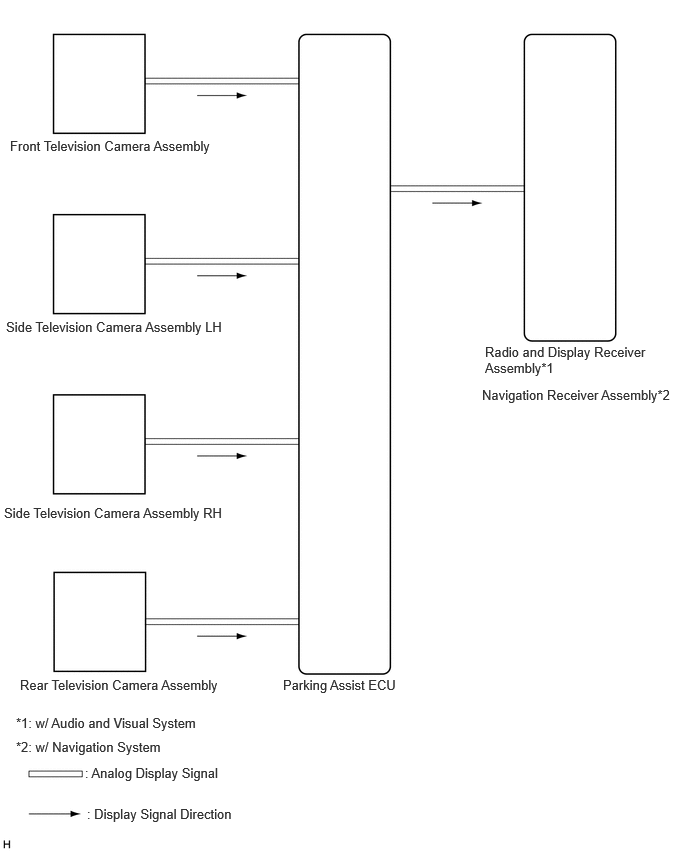
Video signals from the front television camera assembly are input into the parking assist ECU via analog communication lines (vehicle wire harness).
Video signals from the side television camera assembly LH are input into the parking assist ECU via analog communication lines (vehicle wire harness).
Video signals from the side television camera assembly RH are input into the parking assist ECU via analog communication lines (vehicle wire harness).
Video signals from the rear television camera assembly are input into the parking assist ECU via analog communication lines (vehicle wire harness).
Video signals from the parking assist ECU are input into the radio and display receiver assembly*1 or navigation receiver assembly*2 via analog communication lines (vehicle wire harness).
*1: w/ Audio and Visual System
*2: w/ Navigation System
Screen display
Video signals input from each camera are processed in the parking assist ECU and displayed on the radio and display receiver assembly*1 or navigation receiver assembly*2 as the panoramic view monitor system screen.
*1: w/ Audio and Visual System
*2: w/ Navigation System
DIAGNOSTIC FUNCTION OUTLINE
This panoramic view monitor system has a diagnostic function displayed in the radio and display receiver assembly*1 or navigation receiver assembly*2. This function enables the calibration (adjustment and verification) of the panoramic view monitor system.
*1: w/ Audio and Visual System
*2: w/ Navigation System
The panoramic view monitor system can check the following items by using the GTS.
| Item | Contents | Proceed to |
|---|---|---|
| DTC | Diag code can be read and erased | - |
| RoB | Vehicle control history can be read and erased | ( 202304,202405,_56,_083082,_0586733,RM1000000029R9N,202405,999999,_56,_083082,_0586733,RM100000002LW4X,) 202304,202405,_56,_083082,_0586733,RM1000000029R9N,202405,999999,_56,_083082,_0586733,RM100000002LW4X,)
|
| Data List / Active Test | ECU data can be checked | (202304,999999,_56,_083082,_0586733,RM1000000029R9L,)
|
| Freeze frame data | Confirmation of vehicle control history occurrence status is possible | (202304,999999,_56,_083082,_0586733,RM1000000029R9K,)
|
CALIBRATION
Use the panoramic view monitor system diagnosis screen for calibration and checking of the panoramic view monitor system.
- NOTICE:
-
Part replacement and work performed during servicing may require calibration of the panoramic view monitor system and other systems.