DOOR / HATCH POWER BACK DOOR SYSTEM B222631 PBD Unit Pulse Sensor LH Circuit No Signal
DESCRIPTION
This DTC is output when the multiplex network door ECU detects a power back door unit assembly set LH pulse malfunction.
| DTC No. | Detection Item | DTC Detection Condition | Trouble Area |
|---|---|---|---|
| B222631 | PBD Unit Pulse Sensor LH Circuit No Signal | Multiplex network door ECU detects power back door unit assembly set LH pulse malfunction | ·
Multiplex network door ECU ·
Power back door unit assembly set LH ·
Harness or connector |
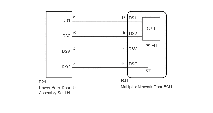
WIRING DIAGRAM
CAUTION / NOTICE / HINT
- NOTICE:
-
If the multiplex network door ECU has been replaced, or if any of the connectors has been disconnected, initialize the power back door system.
PROCEDURE
Clear the DTCs.
- Body Electrical > Back Door > Clear DTCs
- 50002 489
- Result:
Proceed to NEXT
NEXT
Perform a power back door open or close operation.
- Result:
Proceed to NEXT
NEXT
Check for DTCs.
- Body Electrical > Back Door > Trouble Codes
- 50001 489
- Result:
Result Proceed to B222631 is output A B222631 is not output B
A
B
Disconnect the R31 multiplex network door ECU connector.
Disconnect the R21 power back door unit assembly set LH connector.
Measure the resistance according to the value(s) in the table below.
- Standard Resistance:
Tester Connection Condition Specified Condition R31-11 (DSG) - R21-4 (DSG) Always Below 1 Ω R31-4 (DSV) - R21-3 (DSV) Always Below 1 Ω R31-5 (DS2) - R21-6 (DS2) Always Below 1 Ω R31-13 (DS1) - R21-5 (DS1) Always Below 1 Ω R31-11 (DSG) or R21-4 (DSG) - Body ground Always 10 kΩ or higher R31-4 (DSV) or R21-3 (DSV) - Body ground Always 10 kΩ or higher R31-5 (DS2) or R21-6 (DS2) - Body ground Always 10 kΩ or higher R31-13 (DS1) or R21-5 (DS1) - Body ground Always 10 kΩ or higher
- Result:
Proceed to OK NG
OK
NG
Disconnect the R21 power back door unit assembly set LH connector.
Measure the resistance according to the value(s) in the table below.
- Standard Resistance:
Tester Connection Condition Specified Condition R21-4 (DSG) - Body ground Always Below 1 Ω
Measure the voltage according to the value(s) in the table below.
- Standard Voltage:
Tester Connection Condition Specified Condition R21-5 (DS1) - Body ground Ignition switch off 7 V or higher R21-6 (DS2) - Body ground Ignition switch off 7 V or higher R21-3 (DSV) - Body ground Ignition switch off 7 V or higher
- Result:
Proceed to OK NG
OK
NG
Using an oscilloscope, check the waveform of each terminal from the rear of the multiplex network door ECU connector.
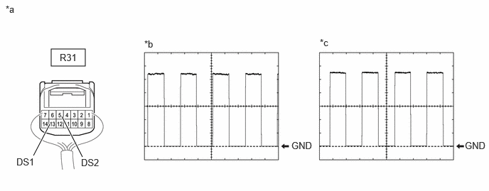
| *a | Component with harness connected
(Multiplex Network Door ECU) |
*b | Waveform (CH1) |
| *c | Waveform (CH2) | - | - |
- Measurement Condition:
Item Condition Tester Connection ·CH1: R31-13 (DS1) - Body ground
·CH2: R31-5 (DS2) - Body ground
Tool Setting 2 V/DIV., 2 ms./DIV. Vehicle Condition Open and close the back door by hand.
- HINT:
- ·
The period changes in accordance to the speed at which the back door is opened and closed by hand.
·The wave height changes in accordance with the auxiliary battery voltage.
- Result:
Proceed to OK NG
OK
NG