M20C-FKS ENGINE CONTROL SFI SYSTEM Active Control Engine Mount System
DESCRIPTION
WIRING DIAGRAM
CAUTION / NOTICE / HINT
- NOTICE:
-
Inspect the fuses for circuits related to this system before performing the following procedure.
PROCEDURE
Connect the GTS to the DLC3.
Turn the ignition switch to ON.
Turn the GTS on.
Enter the following menus: Powertrain / Engine / Active Test / Activate the ACM Inhibit.
- Powertrain > Engine > Active Test
-
Tester Display Activate the ACM Inhibit - 50004 372 43
According to the display on the GTS, perform the Active Test to operate the vacuum switching valve (for active control engine mount system) and for check the operating sound of the vacuum switching valve (for active control engine mount system).
- OK:
Operating sounds can be heard.
- Result:
Proceed to OK NG
OK
NG
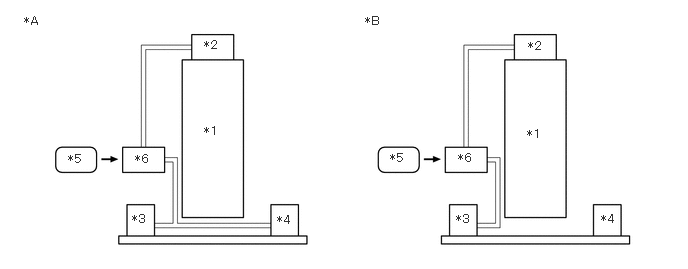
| *A | for 2WD | *B | for AWD |
| *1 | Engine | *2 | Vacuum Pump Assembly |
| *3 | Front Engine Mounting Insulator | *4 | Rear Engine Mounting Insulator |
| *5 | ECM | *6 | Vacuum Switching Valve (for Active Control Engine Mount System) |
Check the air and vacuum hoses for looseness, disconnection and blockage.
- OK:
No looseness, disconnection or blockage.
- Result:
Proceed to OK NG
OK
NG
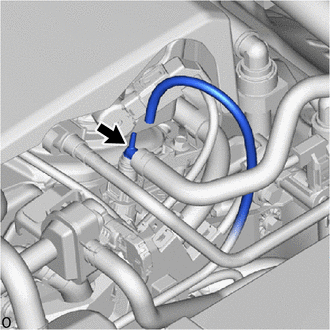
Disconnect the vacuum hose from the vacuum pump assembly.
Start the engine.
Check that the disconnected port located on the vacuum pump assembly applies suction to your finger.
- OK:
Vacuum exists.
- Result:
Proceed to OK NG
OK
NG
Inspect the front engine mounting insulator.
- Result:
Result Proceed to OK (for 2WD) A OK (for AWD) B NG C
A
B
C
Inspect the rear engine mounting insulator.
- Result:
Proceed to OK NG
OK
NG
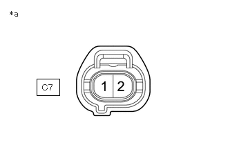
| *a | Front view of wire harness connector
(to Vacuum Switching Valve (for Active Control Engine Mount System)) |
Disconnect the vacuum switching valve (for active control engine mount system) connector.
Turn the ignition switch to ON.
Measure the voltage according to the value(s) in the table below.
- Standard Voltage:
Tester Connection Switch Condition Specified Condition C7-1 - Body ground Ignition switch ON 11 to 14 V
- Result:
Proceed to OK NG
OK
NG
Inspect the vacuum switching valve (for active control engine mount system).
- Result:
Proceed to OK NG
OK
NG
Disconnect the vacuum switching valve (for active control engine mount system) connector.
Disconnect the ECM connector.
Measure the resistance according to the value(s) in the table below.
- Standard Resistance:
Tester Connection Condition Specified Condition C7-2 - C71-108 (ACM) Always Below 1 Ω C7-2 or C71-108 (ACM) - Body ground and other terminals Always 10 kΩ or higher
- Result:
Proceed to OK NG
OK
NG