PARKING BRAKE ELECTRIC PARKING BRAKE SYSTEM(for Gasoline Model) C061013 Right Electric Parking Brake Actuator Control Circuit Open
DESCRIPTION
| DTC No. | Detection Item | DTC Detection Condition | Trouble Area | Memory | Note |
|---|---|---|---|---|---|
| C061013 | Right Electric Parking Brake Actuator Control Circuit Open | ·
Diagnosis Condition: Electric parking brake not operating ·
Malfunction Status: The ECU power supply is normal but there is a malfunction in the electric parking brake actuator RH internal circuit (open). ·
Detection Time: Approximately 0.015 to 0.195 seconds (depending on each malfunction) |
·
Parking brake actuator assembly RH ·
No. 1 parking brake wire assembly ·
Wire harness or connector ·
Skid control ECU (brake actuator assembly) |
DTC stored | An electric parking brake system malfunction is displayed on the multi-information display. |
WIRING DIAGRAM
CAUTION / NOTICE / HINT
- NOTICE:
- ·
The electric parking brake may still operate up to 20 seconds after the ignition switch is turned off. Before disconnecting connectors or fuses, turn the ignition switch off and wait 20 seconds or more.
·After replacing the skid control ECU (brake actuator assembly), perform acceleration sensor zero point calibration and store system information memorization.
·When replacing the skid control ECU (brake actuator assembly), operate the electric parking brake switch (integration control and panel assembly) as the parking brake indicator light blinks when the ignition switch is first turned to ON.
PROCEDURE
Turn the ignition switch off.
Make sure that there is no looseness at the locking part and the connecting part of the connectors.
- OK:
The connector is securely connected.
Disconnect the MM3 and M49 No. 1 parking brake wire assembly connectors.
Check both the connector case and the terminals for deformation and corrosion.
- OK:
No deformation or corrosion.
Measure the resistance according to the value(s) in the table below.
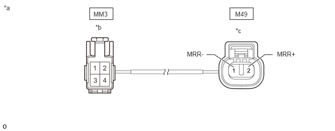
| *a | Front view of No. 1 Parking Brake Wire Assembly | *b | (to Wire Harness Connector) |
| *c | (to Parking Brake Actuator Assembly RH) | - | - |
- Standard Resistance:
Tester Connection Condition Specified Condition MM3-1 - M49-2 (MRR+) Always Below 1 Ω MM3-1 - Other terminals Always 10 kΩ or higher MM3-2 - M49-1 (MRR-) Always Below 1 Ω MM3-2 - Other terminals Always 10 kΩ or higher
- Result:
Proceed to OK NG
OK
NG
Turn the ignition switch off.
Make sure the No. 1 parking brake wire assembly is securely installed.
Disconnect the A39 skid control ECU (brake actuator assembly) connector.
Disconnect the M49 parking brake actuator assembly RH connector.
Measure the resistance according to the value(s) in the table below.
- Standard Resistance:
Tester Connection Condition Specified Condition A39-2 (MRR+) - M49-2 (MRR+) Always Below 1 Ω A39-3 (MRR-) - M49-1 (MRR-) Always Below 1 Ω
- Result:
Proceed to OK NG
OK
NG
Remove the parking brake actuator assembly RH.
Inspect the parking brake actuator assembly RH.
- Result:
Proceed to OK NG
OK
NG