DOOR / HATCH BACK DOOR DISASSEMBLY
CAUTION / NOTICE / HINT
The necessary procedures (adjustment, calibration, initialization, or registration) that must be performed after parts are removed and installed, or replaced during back door disassembly/reassembly are shown below.
| Replaced Part or Performed Procedure | Necessary Procedures | Effect/Inoperative Function When Necessary Procedures are not Performed | Link |
|---|---|---|---|
|
*: Even when not replacing the part, it is necessary to perform the specified necessary procedures after installation. |
|||
| Auxiliary battery terminal is disconnected/reconnected | Reset back door close position | Power Back Door System | ( 202111,999999,_59,_111831,_0505274,RM100000001ZMEG,) 202111,999999,_59,_111831,_0505274,RM100000001ZMEG,)
|
| Rear television camera assembly* | Rear television camera view adjustment | Panoramic View Monitor System | (202409,999999,_56,_111825,_0500432,RM100000002O1F6,)
|
·
Parking assist monitor system initialization ·
Television camera assembly optical axis (Back camera position setting) |
Parking Assist Monitor System | (202409,999999,_56,_111825,_0524148,RM100000002OUWG,)
|
|
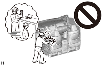
- CAUTION:
-
-
Be sure to read Precaution thoroughly before servicing.
- HINT:
-
When the cable is disconnected / reconnected to the auxiliary battery terminal, systems temporarily stop operating. However, each system has a function that completes learning the first time the system is used.
Learning completes when vehicle is driven Effect/Inoperative Function When Necessary Procedures are not Performed Necessary Procedures Link Lane Tracing Assist System Drive the vehicle straight ahead at 35 km/h (22 mph) or more for 5 seconds or more. ( 202111,999999,_95,_111850,_0502173,RM100000001Z92I,)
Pre-collision System
Learning completes when vehicle is operated normally Effect/Inoperative Function When Necessary Procedures are not Performed Necessary Procedures Link Power Door Lock Control System·Back door opener
Perform door unlock operation with door control switch or electrical key transmitter sub-assembly switch. ( 202111,999999,_58,_111830,_0505351,RM100000001ZMT3,)
Air Conditioning System After the ignition switch is turned to ON, the servo motor standard position is recognized. -
| Replaced Part or Performed Procedure | Necessary Procedures | Effect/Inoperative Function When Necessary Procedures are not Performed | Link |
|---|---|---|---|
|
*: Even when not replacing the part, it is necessary to perform the specified necessary procedures after installation. |
|||
| Auxiliary battery terminal is disconnected/reconnected | Reset back door close position | Power Back Door System | (202111,999999,_59,_111831,_0505274,RM100000001ZMEG,)
|
| Rear television camera assembly* | Rear television camera view adjustment | Panoramic View Monitor System | (202409,999999,_56,_111825,_0500432,RM100000002O1F6,)
|
·
Parking assist monitor system initialization ·
Television camera assembly optical axis (Back camera position setting) |
Parking Assist Monitor System | (202409,999999,_56,_111825,_0524148,RM100000002OUWG,)
|
|
- CAUTION:
-
-
Be sure to read Precaution thoroughly before servicing.
- HINT:
-
When the cable is disconnected / reconnected to the auxiliary battery terminal, systems temporarily stop operating. However, each system has a function that completes learning the first time the system is used.
Learning completes when vehicle is driven Effect/Inoperative Function When Necessary Procedures are not Performed Necessary Procedures Link Lane Tracing Assist System Drive the vehicle straight ahead at 15 km/h (10 mph) or more for 1 seconds or more. ( 202111,999999,_95,_111850,_0502173,RM100000001Z92I,)
Pre-collision System Stop and Start System Idle the engine for approximately 5 to 60 minutes or drive the vehicle until stop and start control is permitted ( 202406,999999,_51,_111803,_0509671,RM100000002KOGF,)
Learning completes when vehicle is operated normally Effect/Inoperative Function When Necessary Procedures are not Performed Necessary Procedures Link Power Door Lock Control System·Back door opener
Perform door unlock operation with door control switch or electrical key transmitter sub-assembly switch. ( 202111,999999,_58,_111830,_0505351,RM100000001ZMT3,)
Air Conditioning System After the ignition switch is turned to ON, the servo motor standard position is recognized. -
PROCEDURE

 67939B
1.REMOVE BACK DOOR CENTER GARNISH
67939B
1.REMOVE BACK DOOR CENTER GARNISH
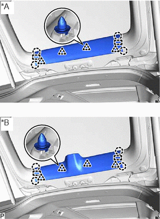
| *A | w/o Digital Inner Mirror |
| *B | w/ Digital Inner Mirror |
Disengage the 4 claws, 4 clips and 2 guides to remove the back door center garnish.
67938A
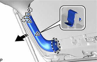
2.REMOVE BACK DOOR SIDE GARNISH LH

|
Place Hand Here |

|
Remove in this Direction |
Disengage the 2 clips, 2 claws and 2 guides to remove the back door side garnish LH as shown in the illustration.
67937B
3.REMOVE BACK DOOR SIDE GARNISH RH
- HINT:
-
Use the same procedure as for the LH side.
74811D
4.REMOVE DOOR PULL HANDLE LH (w/o Power Back Door)
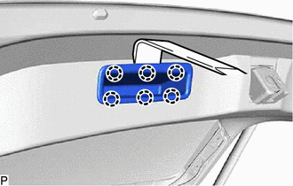
Using a moulding remover, disengage the 6 claws to remove the door pull handle LH.
74811D
5.REMOVE DOOR PULL HANDLE RH (w/o Power Back Door)
- HINT:
-
Use the same procedure as for the LH side.
64785A
6.REMOVE BACK DOOR TRIM BASE (w/ Power Back Door)
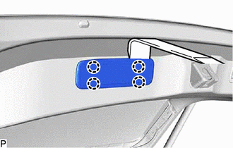
Using a moulding remover, disengage the 4 claws to remove the back door trim base.
74811D
7.REMOVE DOOR PULL HANDLE (w/ Power Back Door)
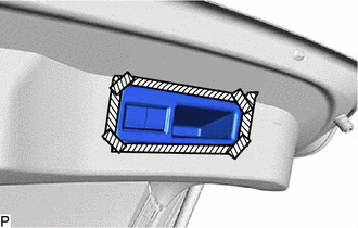

|
Protective Tape |
Apply protective tape to the back door trim board assembly as shown in the illustration.
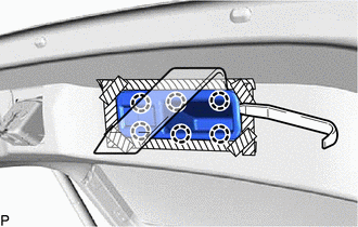
Using a moulding remover, disengage the 6 claws as shown in the illustration.
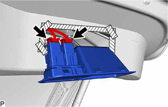
Disconnect the 2 connectors to remove the door pull handle.
67750
8.REMOVE BACK DOOR TRIM BOARD ASSEMBLY
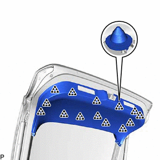
Disengage the 14 clips to remove the back door trim board assembly.
67766
9.REMOVE NO. 2 BACK DOOR SERVICE HOLE COVER

Disengage the 2 claws and 2 guides to remove the No. 2 back door service hole cover.
84280D
10.REMOVE POWER BACK DOOR SENSOR ASSEMBLY LH (w/ Power Back Door)
84270G
11.REMOVE POWER BACK DOOR SENSOR ASSEMBLY RH (w/ Power Back Door)
- HINT:
-
Use the same procedure as for the LH side.
867C0B
12.REMOVE REAR INNER MIRROR CAMERA ASSEMBLY (w/ Digital Inner Mirror)
89222A
13.REMOVE MULTIPLEX NETWORK DOOR ECU (w/ Power Back Door)
67372A
14.REMOVE BACK DOOR WEIGHT
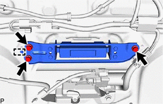
Remove the 3 bolts.
Disengage the guide to remove the back door weight.
69350P
15.REMOVE BACK DOOR LOCK ASSEMBLY WITH COURTESY LIGHT SWITCH (w/o Power Back Door)
69350P
16.REMOVE BACK DOOR LOCK ASSEMBLY WITH COURTESY LIGHT SWITCH (w/ Power Back Door)
67282F
17.REMOVE BACK DOOR LOWER STOPPER LH
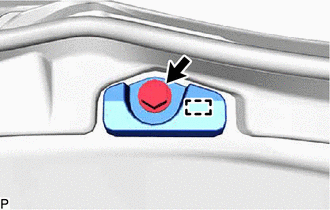
Remove the bolt.
Disengage the guide to remove the back door lower stopper LH.
67281G
18.REMOVE BACK DOOR LOWER STOPPER RH
- HINT:
-
Use the same procedure as for the LH side.
19.REMOVE HOLE PLUG
20.REMOVE REAR SPOILER ASSEMBLY
85292A
21.REMOVE REAR WIPER ARM HEAD CAP
22.REMOVE REAR WIPER ARM AND BLADE ASSEMBLY
85110R
23.REMOVE REAR WIPER MOTOR ASSEMBLY
85143R
24.REMOVE REAR WIPER MOTOR GROMMET
25.REMOVE BACK DOOR OUTSIDE GARNISH SUB-ASSEMBLY WITH LIGHT
812D0
26.REMOVE LICENSE PLATE LIGHT ASSEMBLY WITH BACK DOOR OPENER SWITCH
86790D
27.REMOVE REAR TELEVISION CAMERA ASSEMBLY
67837N
28.REMOVE BACK DOOR DUST PROOF SEAL
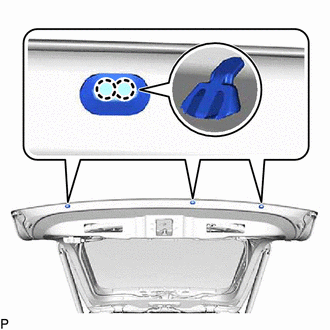
Disengage the 2 claws to remove the back door dust proof seal.
- HINT:
-
Use the same procedure for all back door dust proof seals.
67005B
29.REMOVE BACK DOOR PANEL CUSHION
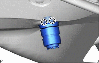
Disengage the 2 claws to remove the back door panel cushion.
- HINT:
-
Use the same procedure for the RH and LH side.
68960B
30.REMOVE BACK DOOR STAY ASSEMBLY LH (w/o Power Back Door)
68970
31.REMOVE BACK DOOR STAY ASSEMBLY RH (w/o Power Back Door)
- HINT:
-
Use the same procedure as for the LH side.
68920
32.REMOVE POWER BACK DOOR UNIT SET ASSEMBLY LH (w/ Power Back Door)
68910A
33.REMOVE POWER BACK DOOR UNIT SET ASSEMBLY RH (w/ Power Back Door)
- HINT:
-
Use the same procedure as for the LH side.
68946
34.REMOVE BACK DOOR DAMPER STAY UPPER BRACKET LH
w/o Power Back Door:
w/ Power Back Door:
68945
35.REMOVE BACK DOOR DAMPER STAY UPPER BRACKET RH
- HINT:
-
Use the same procedure as for the LH side.
68948
36.REMOVE BACK DOOR DAMPER STAY LOWER BRACKET LH
68947
37.REMOVE BACK DOOR DAMPER STAY LOWER BRACKET RH
- HINT:
-
Use the same procedure as for the LH side.