REAR SUSPENSION REAR TRAILING ARM REMOVAL
CAUTION / NOTICE / HINT
The necessary procedures (adjustment, calibration, initialization, or registration) that must be performed after parts are removed and installed, or replaced during rear trailing arm assembly removal/installation are shown below.
| Replaced Part or Performed Procedure | Necessary Procedure | Effect/Inoperative Function when Necessary Procedure not Performed | Link |
|---|---|---|---|
|
*1: Also necessary after performing a tire rotation. *2: It is not necessary to perform this procedure if the tire pressure warning valve and transmitters are installed to the same location. *3: The vehicle height changes because of suspension or tire replacement. |
|||
| Rear wheel alignment adjustment | for HV Model
Perform "Calibration" |
·
DTCs are stored ·
ABS warning light illuminates ·
Brake system warning light (yellow indicator) illuminates ·
Slip indicator light illuminates ·
Electronically controlled brake system does not operate correctly |
( 202203,999999,_54,_111814,_0500722,RM1000000022HHI,) 202203,999999,_54,_111814,_0500722,RM1000000022HHI,)
|
for Gasoline Model
Perform "Calibration" |
·
DTCs are stored ·
ABS warning light illuminates ·
Slip indicator light illuminates ·
Electronically controlled brake system does not operate correctly |
(202203,999999,_54,_111814,_0500728,RM1000000022HI0,)
|
|
| Tires | ·
Initialization*1*2 ·
Tire Position Identification*1*2 |
Tire Pressure Warning System | Refer to Procedures Necessary When Replacing Parts (for Tire Pressure Warning System)
( 202409,999999,_V1,_111780,_0504977,RM100000002OMBP,)
|
| Suspension parts*3 | Parking assist ECU initialization | Panoramic View Monitor System | (202409,999999,_56,_111825,_0500432,RM100000002O1F6,)
|
| Rear television camera assembly optical axis (Back camera position setting) | Parking Assist Monitor System | (202409,999999,_56,_111825,_0524148,RM100000002OUWG,)
|
|
CAUTION / NOTICE / HINT
- HINT:
- ·
Use the same procedure for the RH side and LH side.
·The following procedure is for the LH side.
PROCEDURE

 1.REMOVE REAR WHEEL
51420
2.REMOVE NO. 2 ENGINE UNDER COVER ASSEMBLY (for Gasoline Model)
58166A
3.REMOVE FRONT FLOOR COVER LH (for Gasoline Model LH Side)
58399D
4.REMOVE NO. 2 FLOOR UNDER COVER (for Gasoline Model LH Side)
58166A
5.REMOVE FRONT FLOOR COVER RH (for Gasoline Model RH Side)
58398F
6.REMOVE NO. 1 FLOOR UNDER COVER (for Gasoline Model RH Side)
890C0A
7.SEPARATE NO. 2 PARKING BRAKE WIRE ASSEMBLY
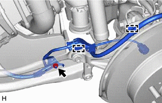
Disengage the 2 clamps.
Remove the nut and separate the No. 2 parking brake wire assembly from the rear trailing arm assembly.
48780E
8.REMOVE REAR TRAILING ARM ASSEMBLY
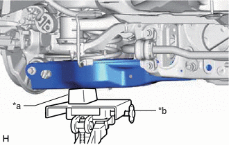
| *a | Wooden Block |
| *b | Transmission Jack |
Using a transmission jack and a wooden block, support the rear No. 2 suspension arm assembly.
- NOTICE:
- ·
When jacking up the rear No. 2 suspension arm assembly, be sure to jack it up slowly.
·Make sure to perform this operation with the vehicle kept as low as possible.
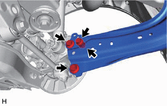
Remove the 3 bolts, nut and separate the rear trailing arm assembly from the rear axle carrier sub-assembly.

Remove the 2 bolts and rear trailing arm assembly.