REAR SUSPENSION REAR LOWER ARM REMOVAL
CAUTION / NOTICE / HINT
The necessary procedures (adjustment, calibration, initialization, or registration) that must be performed after parts are removed and installed, or replaced during rear suspension arm assembly removal/installation are shown below.
| Replaced Part or Performed Procedure | Necessary Procedure | Effect/Inoperative Function when Necessary Procedure not Performed | Link |
|---|---|---|---|
|
*1: Also necessary after performing a tire rotation. *2: It is not necessary to perform this procedure if the tire pressure warning valve and transmitters are installed to the same location. *3: The vehicle height changes because of suspension or tire replacement. |
|||
| Rear wheel alignment adjustment | for HV Model
Perform "Calibration" |
·
DTCs are stored ·
ABS warning light illuminates ·
Brake system warning light (yellow indicator) illuminates ·
Slip indicator light illuminates ·
Electronically controlled brake system does not operate correctly |
( 202203,999999,_54,_111814,_0500722,RM1000000022HHI,) 202203,999999,_54,_111814,_0500722,RM1000000022HHI,)
|
for Gasoline Model
Perform "Calibration" |
·
DTCs are stored ·
ABS warning light illuminates ·
Slip indicator light illuminates ·
Electronically controlled brake system does not operate correctly |
(202203,999999,_54,_111814,_0500728,RM1000000022HI0,)
|
|
| Tires | ·
Initialization*1*2 ·
Tire Position Identification*1*2 |
Tire Pressure Warning System | Refer to Procedures Necessary When Replacing Parts (for Tire Pressure Warning System)
( 202409,999999,_V1,_111780,_0504977,RM100000002OMBP,)
|
| Suspension parts*3 | Parking assist ECU initialization | Panoramic View Monitor System | (202409,999999,_56,_111825,_0500432,RM100000002O1F6,)
|
| Rear television camera assembly optical axis (Back camera position setting) | Parking Assist Monitor System | (202409,999999,_56,_111825,_0524148,RM100000002OUWG,)
|
|
CAUTION / NOTICE / HINT
- HINT:
- ·
Use the same procedure for the RH side and LH side.
·The following procedure is for the LH side.
PROCEDURE

 1.REMOVE REAR WHEEL
48840A
2.REMOVE REAR STABILIZER LINK ASSEMBLY
48231B
3.REMOVE REAR COIL SPRING
48258C
4.REMOVE REAR LOWER COIL SPRING INSULATOR
48740F
5.REMOVE REAR NO. 2 SUSPENSION ARM ASSEMBLY
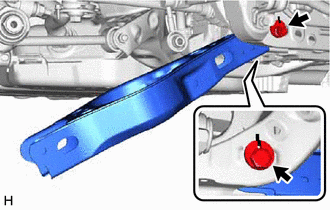
Remove the nut, No. 2 camber adjust cam, rear suspension toe adjust cam sub-assembly and rear No. 2 suspension arm assembly.
- NOTICE:
-
Hold the rear suspension toe adjust cam sub-assembly while rotating the nut.
48720A
6.REMOVE REAR NO. 1 SUSPENSION ARM ASSEMBLY
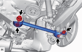
Remove the 2 bolts, 2 nuts and rear No. 1 suspension arm assembly from the rear axle carrier sub-assembly and rear suspension member sub-assembly.
- NOTICE:
-
Because the nut has its own stopper, do not turn the nut. Loosen the bolt with the nut secured.