NAVIGATION / MULTI INFO DISPLAY NAVIGATION SYSTEM Dimmer Signal Circuit
DESCRIPTION
The main body ECU (multiplex network body ECU) sends an auto dimmer signal to the navigation receiver assembly via this circuit.
When the navigation receiver assembly receives an auto dimmer signal from the main body ECU (multiplex network body ECU), the navigation receiver assembly causes the instrument panel illumination to be dimmed.
WIRING DIAGRAM
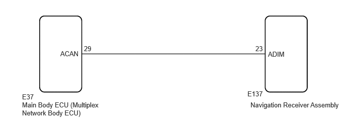
CAUTION / NOTICE / HINT
- NOTICE:
- ·
Before replacing the main body ECU (multiplex network body ECU) is replaced, refer to Service Bulletin.
PROCEDURE
Disconnect the E137 navigation receiver assembly connector.
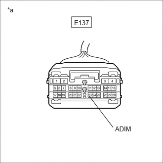
| *a | Front view of wire harness connector
(to Navigation Receiver Assembly) |
Measure the voltage according to the value(s) in the table below.
- Standard Voltage:
Tester Connection Condition Specified Condition Click Location & Routing(E137)Location & Routingewd_type=routing;type=c;code=E137
Click Connector(E137)Instrument Panel>Instrument Panel Wire / Telephone Computer Wire>Navigation Receiver Assemblyewd_type=component;type=c;code=E137;pinno=23
E137-23 (ADIM) - Body ground Ignition switch ON
Automatic light control sensor covered by hand, and light control switch in tail or head position9 V or higher
- Result:
Proceed to OK NG
OK
NG
Disconnect the E37 main body ECU (multiplex network body ECU) connector.
Disconnect the E137 navigation receiver assembly connector.
Measure the resistance according to the value(s) in the table below.
- Standard Resistance:
Tester Connection Condition Specified Condition Click Location & Routing(E37,E137)Location & Routingewd_type=routing;type=c,c;code=E37,E137
Click Connector(E37)Instrument Panel>Instrument Panel Wire / Telephone Computer Wire>Multiplex Network Body ECUewd_type=component;type=c;code=E37;pinno=29
Click Connector(E137)Instrument Panel>Instrument Panel Wire / Telephone Computer Wire>Navigation Receiver Assemblyewd_type=component;type=c;code=E137;pinno=23
E37-29 (ACAN) - E137-23 (ADIM) Always Below 1 Ω E37-29 (ACAN) or E137-23 (ADIM) - Body ground Always 10 kΩ or higher
- Result:
Proceed to OK NG
OK
NG