NAVIGATION / MULTI INFO DISPLAY NAVIGATION SYSTEM AVC-LAN Circuit
DESCRIPTION
The navigation system communicates with each device via AVC-LAN communication. If a malfunction such as a short in a communication line, short to +B or short to ground occurs in the AVC-LAN circuit, communication will stop and the navigation system will not operate correctly. The malfunctioning device can be identified if the system returns to normal when the malfunctioning device is disconnected from the AVC-LAN circuit.
WIRING DIAGRAM
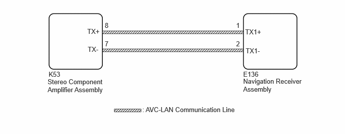
CAUTION / NOTICE / HINT
- NOTICE:
-
Depending on the parts that are replaced during vehicle inspection or maintenance, performing initialization, registration or calibration may be needed. Refer to Precaution for Navigation System.
- HINT:
-
The navigation receiver assembly is the master unit.
PROCEDURE
Disconnect the connector of each dealer installed optional device (AVC-LAN compatible device) and check if the malfunction continues.
- Result:
Result Proceed to No dealer installed optional devices are installed A The malfunction reoccurs The system returns to normal B
A
B
Remove the navigation receiver assembly.

| *a | Component without harness connected
(Navigation Receiver Assembly) |
Measure the resistance according to the value(s) in the table below.
- Standard Resistance:
Tester Connection Condition Specified Condition 1 (TX1+) - 2 (TX1-) Always 60 to 80 Ω
- Result:
Proceed to OK NG
OK
NG
Disconnect the E136 navigation receiver assembly connector.
Disconnect the K53 stereo component amplifier assembly connector.
Measure the resistance according to the value(s) in the table below.
- Standard Resistance:
Tester Connection Condition Specified Condition Click Location & Routing(K53,E136)Location & Routingewd_type=routing;type=c,c;code=K53,E136
Click Connector(K53)Body>Floor Wire>Stereo Component Amplifier Assemblyewd_type=component;type=c;code=K53;pinno=8,7
Click Connector(E136)Instrument Panel>Instrument Panel Wire / Telephone Computer Wire>Navigation Receiver Assemblyewd_type=component;type=c;code=E136;pinno=1,2
K53-8 (TX+) - E136-1 (TX1+) Always Below 1 Ω K53-7 (TX-) - E136-2 (TX1-) Always Below 1 Ω K53-8 (TX+) - Body ground Always 10 kΩ or higher K53-7 (TX-) - Body ground Always 10 kΩ or higher
- Result:
Proceed to OK NG
OK
NG
Measure the voltage according to the value(s) in the table below.
- Standard Voltage:
Tester Connection Switch Condition Specified Condition Click Location & Routing(E136)Location & Routingewd_type=routing;type=c;code=E136
Click Connector(E136)Instrument Panel>Instrument Panel Wire / Telephone Computer Wire>Navigation Receiver Assemblyewd_type=component;type=c;code=E136;pinno=1,2
E136-1 (TX1+) - E136-2 (TX1-) Ignition Switch ACC Approximately 0 V E136-1 (TX1+) - Body ground Ignition Switch ACC Approximately 2.5 V E136-2 (TX1-) - Body ground Ignition Switch ACC Approximately 2.5 V
- Result:
Proceed to OK NG
OK
NG