AUDIO / VIDEO RADIO ANTENNA CORD(for Roof) INSTALLATION
PROCEDURE

 86101Q
1.INSTALL NO. 4 ANTENNA CORD SUB-ASSEMBLY
86101Q
1.INSTALL NO. 4 ANTENNA CORD SUB-ASSEMBLY
Engage the 3 clamps.
Install the No. 4 antenna cord sub-assembly with the bolt.
- Torque:
- 10 N*m (102 kgf*cm, 7 ft.*lbf)
Connect the connector.
86101J
2.INSTALL NO. 2 ANTENNA CORD SUB-ASSEMBLY (for Short Type Panoramic Fixed Moon Roof)
- HINT:
-
Butyl tape and adhesive tape are not available as supply parts. If these pieces of tape still have enough adhesion to secure the No. 2 antenna cord sub-assembly to the roof headlining assembly, reuse them. If the adhesive tape and/or the butyl tape is no longer sticky, apply new tape following the procedure below.
Apply new butyl tape.
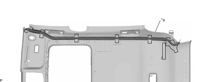
| *a | Marking | - | - |

|
Butyl tape | - | - |
Remove the old butyl tape from the roof headlining assembly.
Prepare an appropriate amount of new butyl tape.
- HINT:
-
Be careful not to touch the adhesive surface.
Apply the butyl tape to the roof headlining assembly while aligning the tape with the markings on the roof headlining assembly.
Peel off the release paper from the butyl tape.
Align the marking tape (A) on the No. 2 antenna cord sub-assembly with the protrusion on the front of the roof headlining assembly and wrap tape around the No. 2 antenna cord sub-assembly and protrusion of the roof headlining assembly.
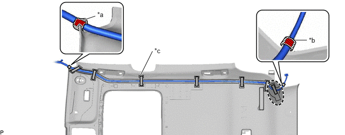
| *a | Marking Tape (A) | *b | Marking Tape (B) |
| *c | Marking | - | - |

|
Adhesive Tape | 
|
Adjustment Area |
Align the marking tape (B) on the No. 2 antenna cord sub-assembly with the protrusion on the rear of the roof headlining assembly and wrap tape around the No. 2 antenna cord sub-assembly and protrusion of the roof headlining assembly.
Install the No. 2 antenna cord sub-assembly to the roof headlining assembly.
- NOTICE:
- ·
Make sure that there are no gaps between the roof headlining assembly and No. 2 antenna cord sub-assembly, and that the No. 2 antenna cord sub-assembly is not twisted.
·Make sure the No. 2 antenna cord sub-assembly is securely installed. If any part of the No. 2 antenna cord sub-assembly is loose, it will cause an abnormal noise.
- HINT:
-
Secure the extra length of the No. 2 antenna cord sub-assembly in the adjustment area.
Apply the adhesive tape as shown in the illustration to secure the No. 2 antenna cord sub-assembly.
86101J
3.INSTALL NO. 2 ANTENNA CORD SUB-ASSEMBLY (for Long Type Panoramic Fixed Moon Roof)
- HINT:
-
Butyl tape and adhesive tape are not available as supply parts. If these pieces of tape still have enough adhesion to secure the No. 2 antenna cord sub-assembly to the roof headlining assembly, reuse them. If the adhesive tape and/or the butyl tape is no longer sticky, apply new tape following the procedure below.
Apply new butyl tape.
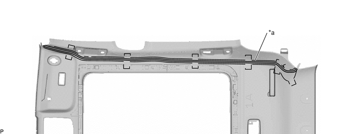
| *a | Marking | - | - |
|
|
Butyl tape | - | - |
Remove the old butyl tape from the roof headlining assembly.
Prepare an appropriate amount of new butyl tape.
- HINT:
-
Be careful not to touch the adhesive surface.
Apply the butyl tape to the roof headlining assembly while aligning the tape with the markings on the roof headlining assembly.
Peel off the release paper from the butyl tape.
Align the marking tape (A) on the No. 2 antenna cord sub-assembly with the protrusion on the front of the roof headlining assembly and wrap tape around the No. 2 antenna cord sub-assembly and protrusion of the roof headlining assembly.
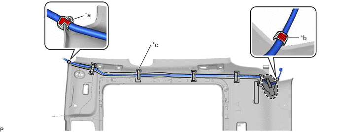
| *a | Marking Tape (A) | *b | Marking Tape (B) |
| *c | Marking | - | - |
|
|
Adhesive Tape |
|
Adjustment Area |
Align the marking tape (B) on the No. 2 antenna cord sub-assembly with the protrusion on the rear of the roof headlining assembly and wrap tape around the No. 2 antenna cord sub-assembly and protrusion of the roof headlining assembly.
Install the No. 2 antenna cord sub-assembly to the roof headlining assembly.
- NOTICE:
- ·
Make sure that there are no gaps between the roof headlining assembly and No. 2 antenna cord sub-assembly, and that the No. 2 antenna cord sub-assembly is not twisted.
·Make sure the No. 2 antenna cord sub-assembly is securely installed. If any part of the No. 2 antenna cord sub-assembly is loose, it will cause an abnormal noise.
- HINT:
-
Secure the extra length of the No. 2 antenna cord sub-assembly in the adjustment area.
Apply the adhesive tape as shown in the illustration to secure the No. 2 antenna cord sub-assembly.
4.INSTALL ROOF HEADLINING ASSEMBLY