SEAT BELT FRONT SEAT OUTER BELT ASSEMBLY REMOVAL
CAUTION / NOTICE / HINT
The necessary procedures (adjustment, calibration, initialization, or registration) that must be performed after parts are removed and installed, or replaced during front seat outer belt assembly removal/installation are shown below.
| Replaced Part or Performed Procedure | Necessary Procedure | Effect/Inoperative Function When Necessary Procedures are not Performed | Link |
|---|---|---|---|
| Auxiliary battery terminal is disconnected/reconnected | Reset back door close position | Power Back Door System | ( 202111,999999,_59,_111831,_0505274,RM100000001ZMEG,) 202111,999999,_59,_111831,_0505274,RM100000001ZMEG,)
|
| Replaced Part or Performed Procedure | Necessary Procedure | Effect/Inoperative Function When Necessary Procedures are not Performed | Link |
|---|---|---|---|
| Auxiliary battery terminal is disconnected/reconnected | Reset back door close position | Power Back Door System | (202111,999999,_59,_111831,_0505274,RM100000001ZMEG,)
|
- HINT:
-
When the cable is disconnected / reconnected to the auxiliary battery terminal, systems temporarily stop operating. However, each system has a function that completes learning the first time the system is used.
Learning completes when vehicle is driven (for HV Model) Effect/Inoperative Function When Necessary Procedures are not Performed Necessary Procedures Link Lane Tracing Assist System Drive the vehicle straight ahead at 35 km/h (22 mph) or more for 5 second or more. ( 202111,999999,_95,_111850,_0502173,RM100000001Z92I,)
Pre-collision System
Learning completes when vehicle is operated normally (for HV Model) Effect/Inoperative Function When Necessary Procedures are not Performed Necessary Procedures Link Power Door Lock Control System
·Back door opener
Perform door unlock operation with door control switch or electrical key transmitter sub-assembly switch. ( 202111,999999,_58,_111830,_0505351,RM100000001ZMT3,)
Air Conditioning System After the ignition switch is turned to ON, the servo motor standard position is recognized. -
Learning completes when vehicle is driven (for Gasoline Model) Effect/Inoperative Function When Necessary Procedures are not Performed Necessary Procedures Link Lane Tracing Assist System Drive the vehicle straight ahead at 15 km/h (10 mph) or more for 1 seconds or more. ( 202111,999999,_95,_111850,_0502173,RM100000001Z92I,)
Pre-collision System Stop and Start System Idle the engine for approximately 5 to 60 minutes or drive the vehicle until stop and start control is permitted ( 202406,999999,_51,_111803,_0509671,RM100000002KOGF,)
Learning completes when vehicle is operated normally (for Gasoline Model) Effect/Inoperative Function When Necessary Procedures are not Performed Necessary Procedures Link Power Door Lock Control System
·Back door opener
Perform door unlock operation with door control switch or electrical key transmitter sub-assembly switch. ( 202111,999999,_58,_111830,_0505351,RM100000001ZMT3,)
Air Conditioning System After the ignition switch is turned to ON, the servo motor standard position is recognized. -
- ·
Use the same procedure for the RH side and LH side.
·The following procedure is for the LH side.
PROCEDURE

 1. PRECAUTION
- CAUTION:
-
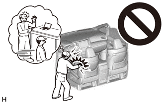
-
Be sure to read Precaution thoroughly before servicing.
- NOTICE:
-
After the ignition switch is turned off, there may be a waiting time before disconnecting the negative (-) auxiliary battery terminal.
2.DISCONNECT CABLE FROM NEGATIVE AUXILIARY BATTERY TERMINAL
for M20C-FKS, M20D-FKS: Click hereGeneral>MAINTENANCE>M20C-FKS, M20D-FKS BATTERY>REMOVAL202406,999999,_V1,_112220,_0503321,RM100000002MSAX_01_0013,
for A25D-FXS, A25F-FXS: Click hereGeneral>MAINTENANCE>A25D-FXS, A25F-FXS AUXILIARY BATTERY>REMOVAL202406,999999,_V1,_112220,_0503322,RM100000002MSAY_01_0013,
- CAUTION:
-
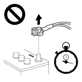
- ·
Wait at least 90 seconds after disconnecting the cable from the negative (-) auxiliary battery terminal to disable the SRS system.
·If an airbag deploys for any reason, it may cause a serious injury.
67914B
3.REMOVE FRONT DOOR SCUFF PLATE
62312B
4.DISCONNECT FRONT DOOR OPENING TRIM WEATHERSTRIP
Disconnect the front door opening trim weatherstrip.
67918A
5.REMOVE REAR DOOR SCUFF PLATE
62332C
6.DISCONNECT REAR DOOR OPENING TRIM WEATHERSTRIP
Disconnect the rear door opening trim weatherstrip.
73233
7.REMOVE LAP BELT OUTER ANCHOR COVER
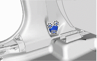
Disengage the 2 claws and guide to remove the lap belt outer anchor cover.
73220
8.DISCONNECT FRONT SEAT OUTER BELT ASSEMBLY
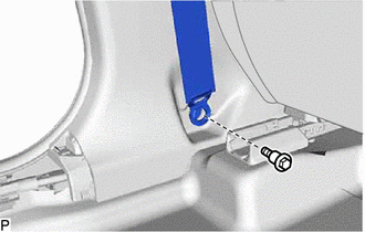
Remove the bolt to disconnect the floor anchor of the front seat outer belt assembly.
62414A
9.REMOVE CENTER PILLAR LOWER GARNISH
62420A
10.REMOVE CENTER PILLAR GARNISH ASSEMBLY
73220
11.REMOVE FRONT SEAT OUTER BELT ASSEMBLY
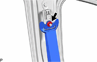
Remove the nut and disconnect the shoulder anchor of the front seat outer belt assembly.
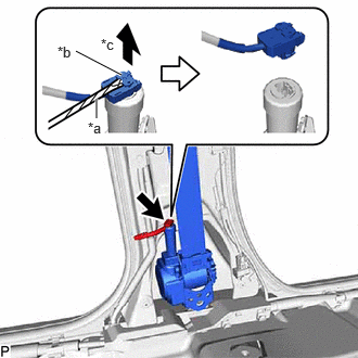
| *a | Protective Tape |
| *b | Locking Button |
| *c | Release |
Using a screwdriver, pull out the locking button as shown in the illustration to release the lock and disconnect the pretensioner connector.
- HINT:
-
Tape the screwdriver tip before use.
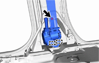
Remove the bolt.
Disengage the 2 guides to remove the front seat outer belt assembly.
73200A
12.REMOVE FRONT SHOULDER BELT ANCHOR ADJUSTER ASSEMBLY
- HINT:
-
Perform this procedure only when replacement of the front shoulder belt anchor adjuster assembly is necessary.
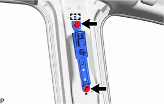
Remove the 2 bolts.
Disengage the guide to remove the front shoulder belt anchor adjuster assembly.