DOOR / HATCH FUEL LID OPENER UNIT REMOVAL
CAUTION / NOTICE / HINT
The necessary procedures (adjustment, calibration, initialization or registration) that must be performed after parts are removed and installed, or replaced during fuel filler opening lid sub-assembly removal/installation are shown below.
| Replaced Part or Performed Procedure | Necessary Procedures | Effect/Inoperative Function When Necessary Procedures are not Performed | Link |
|---|---|---|---|
|
*1: Also necessary after performing a tire rotation. *2: It is not necessary to perform this procedure if the tire pressure warning valve and transmitters are installed to the same location. |
|||
| Auxiliary battery terminal is disconnected/reconnected | Reset back door close position | Power Back Door System | ( 202111,999999,_59,_111831,_0505274,RM100000001ZMEG,) 202111,999999,_59,_111831,_0505274,RM100000001ZMEG,)
|
| Tires | ·
Initialization*1*2 ·
Tire Position Identification*1*2 |
Tire Pressure Warning System | Refer to Procedures Necessary When Replacing Parts (for Tire Pressure Warning System) table below |
- CAUTION:
- ·
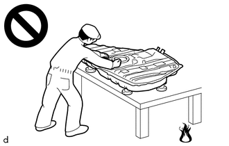
Never perform work on fuel system components near any possible ignition sources.
·Vaporized fuel could ignite, resulting in a serious accident.
·
Do not perform work on fuel system components without first disconnecting the cable from the negative (-) auxiliary battery terminal.
·Sparks could cause vaporized fuel to ignite, resulting in a serious accident.
- HINT:
-
When the cable is disconnected / reconnected to the auxiliary battery terminal, systems temporarily stop operating. However, each system has a function that completes learning the first time the system is used.
Learning completes when vehicle is driven Effect/Inoperative Function When Necessary Procedures are not Performed Necessary Procedures Link Lane Tracing Assist System Drive the vehicle straight ahead at 35 km/h (22 mph) or more for 5 seconds or more. ( 202111,999999,_95,_111850,_0502173,RM100000001Z92I,)
Pre-collision System
Learning completes when vehicle is operated normally Effect/Inoperative Function When Necessary Procedures are not Performed Necessary Procedures Link Power Door Lock Control System·Back door opener
Perform door unlock operation with door control switch or electrical key transmitter sub-assembly switch. ( 202111,999999,_58,_111830,_0505351,RM100000001ZMT3,)
Air Conditioning System After the ignition switch is turned to ON, the servo motor standard position is recognized. -
| Replaced Part or Performed Procedure | Necessary Procedures | Effect/Inoperative Function When Necessary Procedures are not Performed | Link |
|---|---|---|---|
|
*1: Also necessary after performing a tire rotation. *2: It is not necessary to perform this procedure if the tire pressure warning valve and transmitters are installed to the same location. |
|||
| Auxiliary battery terminal is disconnected/reconnected | Reset back door close position | Power Back Door System | (202111,999999,_59,_111831,_0505274,RM100000001ZMEG,)
|
| Tires | ·
Initialization*1*2 ·
Tire Position Identification*1*2 |
Tire Pressure Warning System | Refer to Procedures Necessary When Replacing Parts (for Tire Pressure Warning System) table below |
- CAUTION:
- ·
Never perform work on fuel system components near any possible ignition sources.
·Vaporized fuel could ignite, resulting in a serious accident.
·
Do not perform work on fuel system components without first disconnecting the cable from the negative (-) auxiliary battery terminal.
·Sparks could cause vaporized fuel to ignite, resulting in a serious accident.
- HINT:
-
When the cable is disconnected / reconnected to the auxiliary battery terminal, systems temporarily stop operating. However, each system has a function that completes learning the first time the system is used.
Learning completes when vehicle is driven Effect/Inoperative Function When Necessary Procedures are not Performed Necessary Procedures Link Lane Tracing Assist System Drive the vehicle straight ahead at 15 km/h (10 mph) or more for 1 seconds or more. ( 202111,999999,_95,_111850,_0502173,RM100000001Z92I,)
Pre-collision System Stop and Start System Idle the engine for approximately 5 to 60 minutes or drive the vehicle until stop and start control is permitted ( 202406,999999,_51,_111803,_0509671,RM100000002KOGF,)
Learning completes when vehicle is operated normally Effect/Inoperative Function When Necessary Procedures are not Performed Necessary Procedures Link Power Door Lock Control System·Back door opener
Perform door unlock operation with door control switch or electrical key transmitter sub-assembly switch. ( 202111,999999,_58,_111830,_0505351,RM100000001ZMT3,)
Air Conditioning System After the ignition switch is turned to ON, the servo motor standard position is recognized. -
PROCEDURE

 1. PRECAUTION
- NOTICE:
-
After the ignition switch is turned off, there may be a waiting time before disconnecting the negative (-) auxiliary battery terminal.
58410B
2.REMOVE DECK BOARD ASSEMBLY
71940A
3.REMOVE REAR SEAT HEADREST ASSEMBLY (for SFTM Made)
71940A
4.REMOVE REAR SEAT HEADREST ASSEMBLY (for GTMC Made)
5.REMOVE REAR SEAT CUSHION ASSEMBLY (for SFTM Made)
6.REMOVE REAR SEAT CUSHION ASSEMBLY (for GTMC Made)
72693
7.REMOVE REAR SEAT CUSHION LOCK HOOK (for SFTM Made)
72693
8.REMOVE REAR SEAT CUSHION LOCK HOOK (for GTMC Made)
9.REMOVE REAR SEATBACK ASSEMBLY LH (for SFTM Made)
10.REMOVE REAR SEATBACK ASSEMBLY LH (for GTMC Made)
58416K
11.REMOVE REAR NO. 2 FLOOR BOARD (for HV Model)
65351A
12.REMOVE BATTERY HOLE COVER (for HV Model)
13.DISCONNECT CABLE FROM NEGATIVE AUXILIARY BATTERY TERMINAL
for M20C-FKS, M20D-FKS:
for A25D-FXS, A25F-FXS:
58417
14.REMOVE REAR NO. 3 FLOOR BOARD
64779
15.REMOVE SPARE WHEEL COVER TRAY
58387B
16.REMOVE REAR FLOOR FINISH PLATE
17.SEPARATE REAR SEATBACK BOARD CARPET ASSEMBLY RH (for SFTM Made)
18.SEPARATE REAR SEATBACK BOARD CARPET ASSEMBLY RH (for GTMC Made)
58577E
19.REMOVE REAR NO. 1 FLOOR MAT SUPPORT SIDE PLATE
67918A
20.REMOVE REAR DOOR SCUFF PLATE LH
58467H
21.REMOVE NO. 3 BATTERY SERVICE COVER BOARD (for HV Model)
62332C
22.DISCONNECT REAR DOOR OPENING TRIM WEATHERSTRIP LH
73706
23.REMOVE CHILD RESTRAINT SEAT ANCHOR BRACKET SUB-ASSEMBLY LH
71304C
24.REMOVE REAR SEATBACK HINGE SUB-ASSEMBLY LH
62552F
25.REMOVE REAR SEAT SIDE GARNISH LH
64740C
26.REMOVE DECK TRIM SIDE PANEL ASSEMBLY LH
86150
27.REMOVE NO. 1 SPEAKER ASSEMBLY WITH BOX (for 9 Speakers)
77035
28.DISCONNECT FUEL LID LOCK CONTROL CABLE SUB-ASSEMBLY (for Gasoline Model)
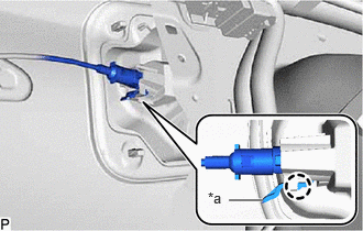
| *a | Stopper |
Release the stopper and disengage the claw.
Disconnect the fuel lid lock control cable sub-assembly.
77030A
29.REMOVE FUEL LID LOCK WITH MOTOR ASSEMBLY (for HV Model)
30.REMOVE REAR WHEEL LH
52592
31.REMOVE REAR BUMPER SIDE SEAL LH
65638
32.DISCONNECT REAR WHEEL HOUSE LINER LH
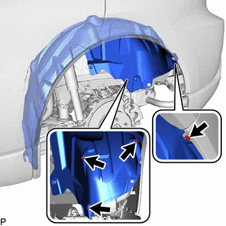
Remove the 4 clips and disconnect the rear wheel house liner LH.
77350
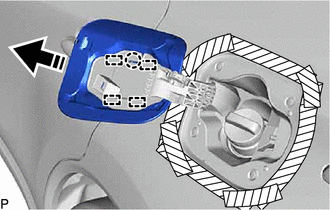
33.REMOVE FUEL FILLER OPENING LID ASSEMBLY
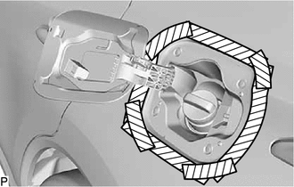

|
Protective Tape |
Apply protective tape around the fuel filler opening lid sub-assembly as shown in the illustration.

|
Remove in this Direction |
Disengage the claw.
Disengage the 4 guides to remove the fuel filler opening lid assembly as shown in the illustration.
77310A
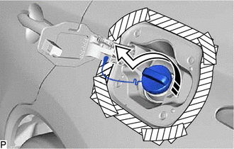
34.REMOVE FUEL TANK CAP ASSEMBLY
|
|
Remove in this Direction |
Remove the fuel tank cap assembly as shown in the illustration.
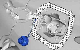
Disengage the clamp to remove the fuel tank cap assembly.
77305A
35.REMOVE FUEL FILLER OPENING LID SUB-ASSEMBLY
Remove the fuel inlet box ring as shown in the illustration.
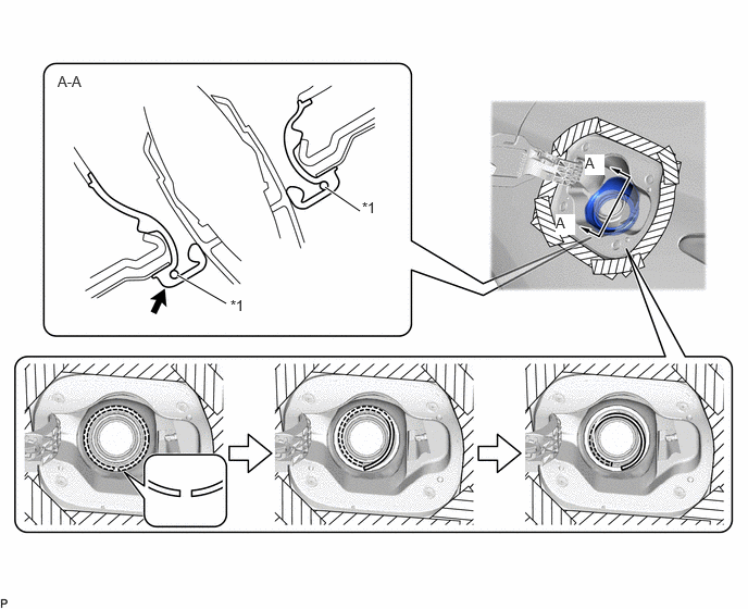
| *1 | Fuel Inlet Box Ring | - | - |

|
Push | - | - |
Disconnect the fuel filler opening lid sub-assembly from the fuel tank filler pipe assembly as shown in the illustration.
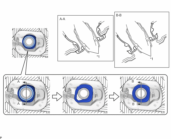
| *1 | Fuel Tank Filler Pipe Assembly | - | - |
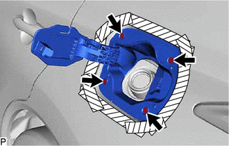
Remove the 4 screws.
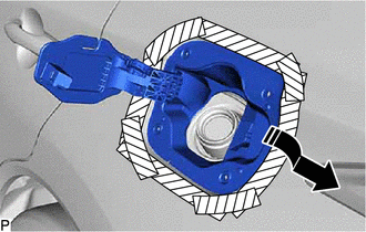
|
|
Remove in this Direction |
Remove the fuel filler opening lid sub-assembly as shown in the illustration.