THEFT DETERRENT / KEYLESS ENTRY SMART ENTRY AND START SYSTEM(for Entry Function, Gasoline Model) Entry Lock/Unlock Functions and Wireless Functions do not Operate After New/Additional Key ID Registration
DESCRIPTION
If all of the following conditions are met after an error message is displayed on the screen of the GTS during registration, or after performing new key ID registration or additional key ID registration, it is suspected that there is an ID code registration failure between the certification ECU (smart key ECU assembly) and main body ECU (multiplex network body ECU), or there is a certification ECU (smart key ECU assembly) or main body ECU (multiplex network body ECU) malfunction.
It is possible to start the engine
Wireless door lock/unlock operation is not possible
Entry lock/unlock operation is not possible
Also, if the engine does not start, refer to the following and perform troubleshooting as the suspected cause is a malfunction of the electrical key transmitter sub-assembly, smart entry and start system (for start function), etc.
WIRING DIAGRAM
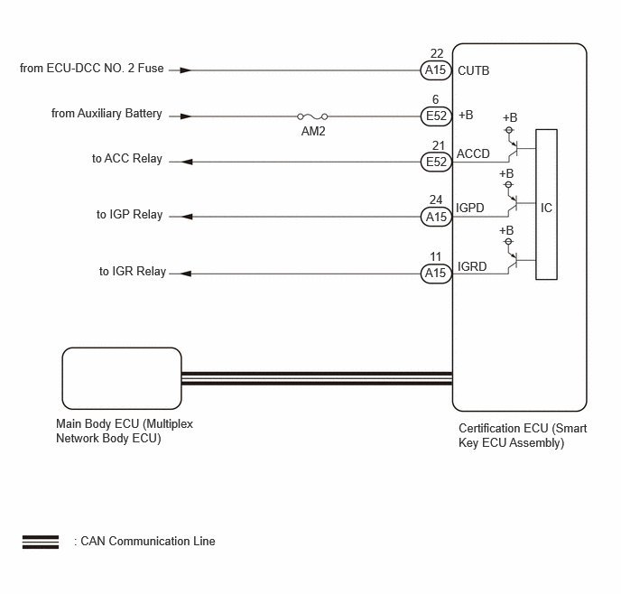
CAUTION / NOTICE / HINT
- NOTICE:
- ·
When using the GTS with the ignition switch off, perform lock and unlock operations using the door control switch of the multiplex network master switch assembly at intervals of 1.5 seconds or less until communication between the GTS and the vehicle begins, and then select the vehicle model manually.
Then select Model Code "KEY REGIST" under manual mode and enter the following menus: Body Electrical / Entry&Start (CAN). While using the GTS, periodically perform lock and unlock operations using the door control switch of the multiplex network master switch assembly at intervals of 1.5 seconds or less to maintain communication between the GTS and the vehicle.
·The smart entry and start system (for Entry Function) uses the CAN communication system. Inspect the communication function by following How to Proceed with Troubleshooting. Troubleshoot the smart entry and start system (for Entry Function) after confirming that the communication systems are functioning properly.
·Before replacing the certification ECU (smart key ECU assembly) or main body ECU (multiplex network body ECU), refer to Service Bulletin.
·It is necessary to perform initialization (Click hereSuspension>TIRE PRESSURE MONITORING>TIRE PRESSURE WARNING RECEIVER>INITIALIZATION202111,999999,_53,_111812,_0502517,RM100000001ZADA,) after registration (Click hereSuspension>TIRE PRESSURE MONITORING>TIRE PRESSURE WARNING RECEIVER>REGISTRATION202111,999999,_53,_111812,_0502517,RM100000001ZAD9,) of the transmitter IDs into the electrical key and tire pressure warning ECU and receiver if the electrical key and tire pressure warning ECU and receiver has been replaced.
·Check that there are no electrical key transmitter sub-assemblies in the vehicle.
·After repair, confirm that no DTCs are output.
·Inspect the fuses for circuits related to this system before performing the following procedure.
PROCEDURE
Using the electrical key transmitter sub-assembly that was used for key ID registration, check if the engine starts.
- OK:
Engine starts normally.
- Result:
Proceed to OK NG
OK
NG
Perform registration of the B code.
- HINT:
-
Refer to Service Bulletin (ECU CODE REGISTRATION).
- Result:
Proceed to NEXT
NEXT
After completing B code registration, check that the entry lock and unlock functions can be operated 2 times consecutively.
- Result:
Result Proceed to Entry function does not operate normally A Entry function operates normally B
A
B
Read the Data List according to the display on the GTS.
- Body Electrical > Entry&Start > Data List
-
Tester Display Measurement Item Range Normal Condition Diagnostic Note B Code Registered B code registration status No or Yes No: B code is not registered properly
Yes: B code is registered properly-
- Body Electrical > Entry&Start > Data List
-
Tester Display B Code Registered - 50003 440 23
- NOTICE:
-
If "No" is displayed on the GTS screen, perform the following procedure again. (maximum of 3 times)
- ·
PERFORM REGISTRATION
·CHECK ENTRY OPERATION
·READ VALUE USING GTS (B CODE REGISTERED)
-
However, if the problem symptoms do not disappear, proceed to the procedure according to Range.
- Result:
Result Proceed to "Yes" is displayed on the GTS A "No" is displayed on the GTS B
A
B
Measure the voltage while checking the Data List on the GTS.
Read the Data List according to the display on the GTS.
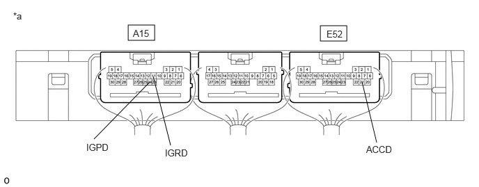
| *a | Component with harness connected
(Certification ECU (Smart Key ECU Assembly)) |
- | - |
- Body Electrical > Power Source Control > Data List
-
Tester Display Measurement Item Range Normal Condition Diagnostic Note Power Supply Condition Power supply state OFF, ACC ON, IGR ON, IGP ON or Starter ON OFF: Ignition switch off
ACC ON: Ignition switch ACC
IGR ON: Ignition switch ON
IGP ON: Ignition switch ON
Starter ON: Sending engine start request signal-
- Body Electrical > Power Source Control > Data List
-
Tester Display Power Supply Condition - 50003 454 405
- Standard Voltage:
Tester Connection Condition Specified Condition Click Location & Routing(A15,E52)Location & Routingewd_type=routing;type=c,c;code=A15,E52
Click Connector(A15)Instrument Panel>Engine Room Main Wire>Smart Key ECU Assemblyewd_type=component;type=c;code=A15;pinno=11,24
Click Connector(E52)Instrument Panel>Instrument Panel Wire / Radio Wiring Sub-Assy / Telephone Computer Wire>Smart Key ECU Assemblyewd_type=component;type=c;code=E52;pinno=21
A15-11 (IGRD) - Body ground Ignition switch off Below 1 V Ignition switch ACC Below 1 V Ignition switch ON 9 V or higher A15-24 (IGPD) - Body ground Ignition switch off Below 1 V Ignition switch ACC Below 1 V Ignition switch ON 9 V or higher E52-21 (ACCD) - Body ground Ignition switch off Below 1 V Ignition switch ACC 8.5 V or higher Ignition switch ON 8.5 V or higher
- Result:
Proceed to OK NG
OK
NG
Read the Data List according to the display on the GTS.
- Body Electrical > Main Body > Data List
-
Tester Display Measurement Item Range Normal Condition Diagnostic Note IGR Power Ignition switch status OFF or ON OFF: Ignition switch off
ON: Ignition switch ON-
- Body Electrical > Main Body > Data List
-
Tester Display IGR Power - 50003 449 122
- HINT:
-
If the certification ECU (smart key ECU assembly) misjudges for any reason that the ignition switch is ON even though the ignition switch is off, the entry lock and unlock functions will be disabled.
- Result:
Result Proceed to The main body ECU (multiplex network body ECU) judges properly that the power source is off when the ignition switch is off A The main body ECU (multiplex network body ECU) does not judge properly that the power source is off when the ignition switch is off B
A
B
Disconnect and reconnect the certification ECU (smart key ECU assembly) connectors.
Check that the function operates normally.
- Result:
Result Proceed to Entry function does not operate normally A Entry function operates normally B
A
B
Replace the certification ECU (smart key ECU assembly) with a new one and perform registration again.
- HINT:
-
Refer to Service Bulletin.
- Result:
Proceed to NEXT
NEXT
Check that the function operates normally.
- Result:
Result Proceed to Wireless door lock function operates normally A Wireless door lock function does not operate normally B
A
B