INTERIOR PANELS / TRIM INSTRUMENT PANEL SAFETY PAD INSTALLATION
PROCEDURE

 1.INSTALL INSTRUMENT PANEL SAFETY PAD SUB-ASSEMBLY
Engage the 5 guides to temporarily install the instrument panel safety pad sub-assembly as shown in the illustration.
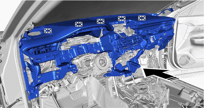

|
Install in this Direction | - | - |
- NOTICE:
- ·
Do not damage the instrument panel safety pad sub-assembly.
·Do not allow the wire harnesses to interfere with the surrounding parts.
Install the instrument panel safety pad sub-assembly with the 5 bolts <B> and nut <E>.
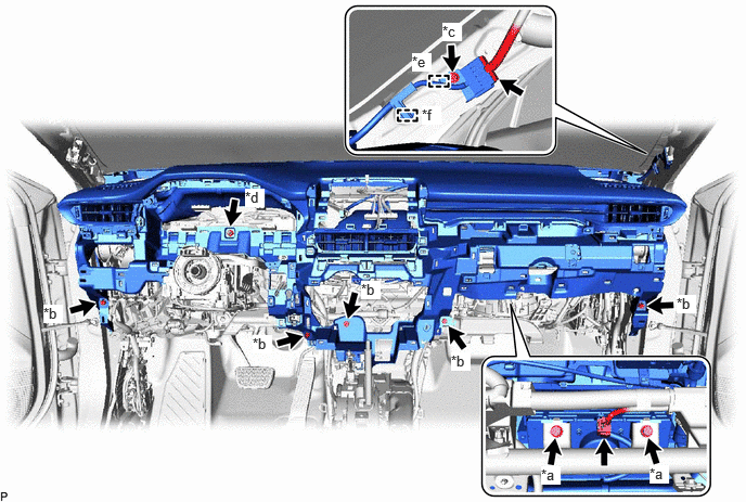
| *a | Bolt <A> | *b | Bolt <B> |
| *c | Bolt <D> | *d | Nut <E> |
| *e | Guide | *f | Clamp |
Connect the airbag connector.
- HINT:
-
Refer to How to Connect or Disconnect Airbag Connector.
Install the 2 bolts <A>.
- Torque:
- 20 N*m (204 kgf*cm, 15 ft.*lbf)
Engage the clamp and guide.
Install the bolt <D>.
- Torque:
- 10 N*m (102 kgf*cm, 7 ft.*lbf)
Connect the connector.
w/ Ion Generator:
Connect the connector.
Engage the clamp.
Engage the 2 claws to connect the cooler (room temp. sensor) thermistor.
Install the 2 clips.
86160J
2.INSTALL FRONT NO. 3 SPEAKER ASSEMBLY (for LH Side)
55525
3.INSTALL NO. 1 SPEAKER HOLE COVER
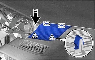
|
|
Install in this Direction |
Engage the 2 guides and 2 clips as shown in the illustration to install the No. 1 speaker hole cover.
62212
4.INSTALL FRONT PILLAR GARNISH LH
86160J
5.INSTALL FRONT NO. 3 SPEAKER ASSEMBLY (for RH Side)
- HINT:
-
Use the same procedure as for the LH side.
55535B
6.INSTALL NO. 2 SPEAKER HOLE COVER
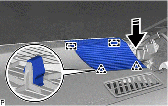
|
|
Install in this Direction |
Engage the 2 guides and 2 clips as shown in the illustration to install the No. 2 speaker hole cover.
62211
7.INSTALL FRONT PILLAR GARNISH RH
- HINT:
-
Use the same procedure as for the LH side.
8.INSTALL TELEMATICS TRANSCEIVER WITH BRACKET
58813
9.INSTALL UPPER CONSOLE BOX (w/o Wireless Charger)
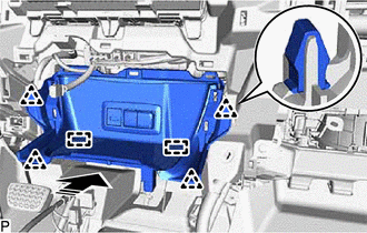
Engage the clamp and connect each connector.
|
|
Install in this Direction |
Engage the 2 guides and 4 clips as shown in the illustration to install the upper console box.
10.INSTALL WIRELESS CHARGER ASSEMBLY (w/ Wireless Charger)
58925B
11.INSTALL UPPER CONSOLE BOX INSULATOR
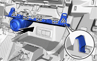
Connect the 2 connectors.
|
|
Install in this Direction |
Engage the 3 guides and 2 clips as shown in the illustration to install the upper console box insulator.
55900
12.INSTALL AIR CONDITIONING CONTROL ASSEMBLY
13.INSTALL RADIO AND DISPLAY RECEIVER ASSEMBLY WITH BRACKET (w/o Navigation System)
14.INSTALL NAVIGATION RECEIVER ASSEMBLY WITH BRACKET (w/ Navigation System)
55422C
15.INSTALL CENTER UPPER INSTRUMENT CLUSTER FINISH PANEL
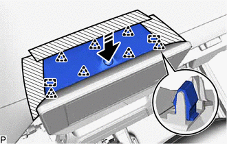
Connect the connector.
|
|
Install in this Direction |
Engage the 2 guides and 7 clips as shown in the illustration to install the center upper instrument cluster finish panel.
83100
16.INSTALL COMBINATION METER ASSEMBLY
55410C
17.INSTALL INSTRUMENT CLUSTER FINISH PANEL ASSEMBLY
|
|
Install in this Direction |
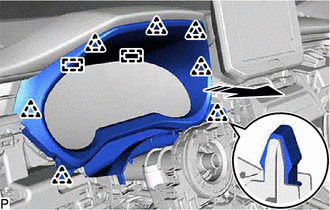
Engage the 2 guides and 7 clips as shown in the illustration to install the instrument cluster finish panel assembly.
73900
18.INSTALL LOWER NO. 1 INSTRUMENT PANEL AIRBAG ASSEMBLY
55480D
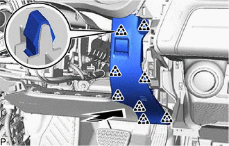
19.INSTALL LOWER INSTRUMENT PANEL FINISH PANEL ASSEMBLY
Connect the connector.
|
|
Install in this Direction |
Engage the 8 clips as shown in the illustration to install the lower instrument panel finish panel assembly.
53601
20.CONNECT HOOD LOCK CONTROL LEVER SUB-ASSEMBLY
Engage the 2 guides and claw to connect the hood lock control lever sub-assembly.
77306
21.CONNECT FUEL LID LOCK OPEN LEVER SUB-ASSEMBLY (for Gasoline Model)
Engage the 2 guides and claw to connect the fuel lid lock open lever sub-assembly.
55545
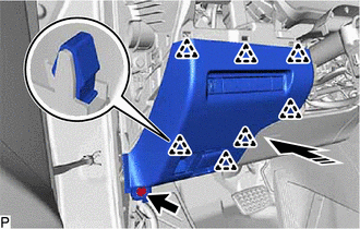
22.INSTALL FUSE BOX OPENING COVER
Connect each connector and engage the clamp.
|
|
Install in this Direction |
Engage the 7 clips as shown in the illustration.
Install the fuse box opening cover with the bolt <B>.
55474C
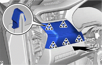
23.INSTALL NO. 1 INSTRUMENT CLUSTER FINISH PANEL GARNISH
|
|
Install in this Direction |
Engage the 5 clips as shown in the illustration to install the No. 1 instrument cluster finish panel garnish.
55433B
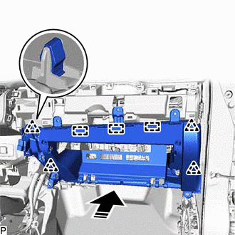
24.INSTALL LOWER NO. 2 INSTRUMENT PANEL FINISH PANEL
|
|
Install in this Direction |
Engage the 3 guides and 4 clips as shown in the illustration.
Install the lower No. 2 instrument panel finish panel with the 5 bolts <B>.
Connect the connector.
25.INSTALL CONSOLE BOX ASSEMBLY
55550
26.INSTALL GLOVE COMPARTMENT DOOR ASSEMBLY
While keeping the glove compartment door assembly open approximately 15° from the position shown in the illustration, engage the 2 hinges by moving it horizontally.
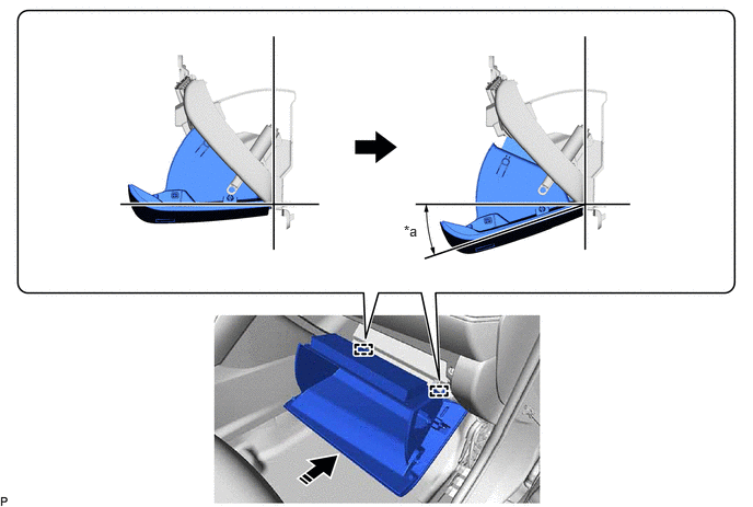
| *a | 15° | - | - |
|
|
Install in this Direction | - | - |
- NOTICE:
-
Engaging the hinges from an upward angle will deform the hinges. Be sure to install the glove compartment door assembly horizontally.
Engage the claw to connect the glove compartment door stopper sub-assembly.
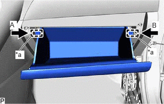
| *a | Stopper |
Slightly bend the stoppers (A) and (B) in the directions indicated by the arrows shown in the illustration and engage the stoppers to install the glove compartment door assembly.
55318F
27.INSTALL NO. 2 INSTRUMENT SIDE PANEL
|
|
Install in this Direction (1) |

|
Install in this Direction (2) |
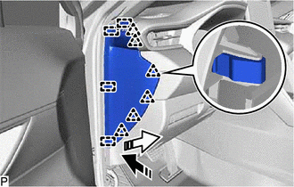
Engage the 4 guides and 6 clips as shown in the illustration to install the No. 2 instrument side panel.
62312B
28.INSTALL FRONT DOOR OPENING TRIM WEATHERSTRIP LH
55606
29.INSTALL NO. 1 INSTRUMENT PANEL UNDER COVER SUB-ASSEMBLY
Engage the clamp and connect the connector.
Engage the 2 claws to connect the DLC3.
|
|
Install in this Direction (1) |
|
|
Install in this Direction (2) |
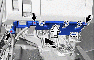
Engage the guide and 3 claws as shown in the illustration.
Install the No. 1 instrument panel under cover sub-assembly with the 3 screws <C>.
62112A
30.INSTALL COWL SIDE TRIM SUB-ASSEMBLY LH
67914B
31.INSTALL FRONT DOOR SCUFF PLATE LH
55607
32.INSTALL NO. 2 INSTRUMENT PANEL UNDER COVER SUB-ASSEMBLY
Engage the clamp and connect the connector.
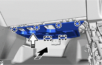
|
|
Install in this Direction (1) |
|
|
Install in this Direction (2) |
Engage the 2 guides and 4 claws as shown in the illustration to install the No. 2 instrument panel under cover sub-assembly.
62111C
33.INSTALL COWL SIDE TRIM BOARD RH
- HINT:
-
Use the same procedure as for the LH side.
67913B
34.INSTALL FRONT DOOR SCUFF PLATE RH
- HINT:
-
Use the same procedure as for the LH side.
84329
35.INSTALL TURN SIGNAL SWITCH
84650
36.INSTALL WINDSHIELD WIPER SWITCH ASSEMBLY
45286B
37.INSTALL UPPER STEERING COLUMN COVER
45287
38.INSTALL LOWER STEERING COLUMN COVER
39.ALIGN FRONT WHEELS FACING STRAIGHT AHEAD
40.INSPECT AND ADJUST SPIRAL CABLE WITH SENSOR SUB-ASSEMBLY
45100
41.INSTALL STEERING WHEEL ASSEMBLY
42.CHECK STEERING WHEEL CENTER POINT
45130
43.INSTALL HORN BUTTON ASSEMBLY