METER / GAUGE / DISPLAY METER / GAUGE SYSTEM(for Optitron Meter Type) TERMINALS OF ECU
COMBINATION METER ASSEMBLY
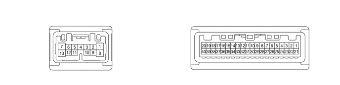
Measure the voltage and resistance and check for pulses according to the value(s) in the table below.
| Terminal No. (Symbol) | Terminal Description | Condition | Specified Condition |
|---|---|---|---|
| E16-1 (ODO) - Body ground | ODO/TRIP switch signal | Ignition switch ON, ODO/TRIP switch not pushed | 4.8 to 5.2 V |
| E16-3 (HAZ) - Body ground | Hazard warning signal switch signal | Hazard warning signal switch off → on | 11 to 14 V → Below 1 V |
| E16-5 (SW3) - Body ground | Ground for trip switch | Always | Below 1 Ω |
| E16-7 (LR) - Body ground | Front/side turn flasher signal
(RH side) |
Turn indicator light (RH) blinking → off | (11 to 14 V ←→ Below 1 V) → Below 1 V |
| E16-8 (B) - Body ground | Power source for auxiliary battery | ·
Ignition switch off*1 ·
Always*2 |
11 to 14 V |
| E16-10 (TRNL) - Body ground | Rear turn flasher signal
(LH side) |
Turn indicator light (LH) blinking → off | (11 to 14 V ←→ Below 1 V) → Below 1 V |
| E16-11 (LL) - Body ground | Front/side turn flasher signal
(LH side) |
Turn indicator light (LH) blinking → off | (11 to 14 V ←→ Below 1 V) → Below 1 V |
| E16-13 (TRNR) - Body ground | Rear turn flasher signal
(RH side) |
Turn indicator light (RH) blinking → off | (11 to 14 V ←→ Below 1 V) → Below 1 V |
| E17-2 (EP) - Body ground | Ground | Always | Below 1 Ω |
| E17-5 (SI) - Body ground | Vehicle speed signal (Input) | Ignition switch ON, wheel being rotated | Pulse generation
(See waveform 1) |
| E17-6 (+S) - Body ground | Vehicle speed signal (Output) | Ignition switch ON, wheel being rotated | Pulse generation
(See waveform 1) |
| E17-12 (SW) - Body ground*2 | Brake fluid level signal | Ignition switch ON, brake fluid level not low (brake warning light/red (malfunction) off) → low (brake warning light/red (malfunction) on) | 11 to 14 V → Below 1 V |
| E17-14 (FR) - E17-33 (FE&B) | Fuel level signal | Ignition switch ON, fuel receiver gauge indicates F → E (fuel level warning light on) | Pulse generation
(See waveform 2) |
| E17-15 (FV) - Body ground | Power source for fuel sender gauge | Ignition switch ON | Pulse generation
(See waveform 3) |
| E17-21 (ES) - Body ground | Ground | Always | Below 1 Ω |
| E17-27 (OILW) - Body ground*1 | Engine oil level signal | Ignition switch ON, engine oil level not low → low | Below 1 V → 11 to 14 V |
| E17-28 (FR2) - E17-33 (FE&B)*2 | Fuel level signal | Ignition switch ON, fuel receiver gauge indicates F → E (fuel level warning light on) | Pulse generation
(See waveform 2) |
| E17-29 (MSM+) - Body ground | Steering pad switch signal | Ignition switch ON, OK and back switches on steering pad switch not pushed | 4.8 to 5.2 V |
| E17-30 (MSTI) - Body ground | Steering pad switch signal | Ignition switch ON, up, down, left and right switches on steering pad switch not pushed | 4.8 to 5.2 V |
| E17-31 (CANL) - Body ground | CAN communication signal | Ignition switch ON | Pulse generation |
| E17-32 (CANH) - Body ground | CAN communication signal | Ignition switch ON | Pulse generation |
| E17-33 (FE&B) - Body ground | Ground for fuel sender gauge | Always | Below 1 Ω |
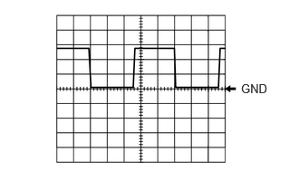
| E17-34 (LST1) - Body ground*1 | Fuel lid operation signal | Ignition switch OFF | 11 to 14 V |
| The following message (interrupt display) being displayed on the multi-information display:
"Ready to Refuel" |
Pulse generation
(See waveform 4) |
||
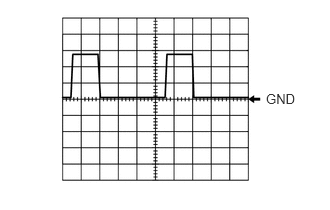
| The following message (interrupt display) being displayed on the multi-information display:
"Close Fuel Lid" |
Pulse generation
(See waveform 5) |
||
| The following message (interrupt display) being displayed on the multi-information display:
"Please Wait Fuel Door Opening" |
Pulse generation
(See waveform 6) |
||
| E17-36 (MSCH) - Body ground*3 | Local bus communication signal | Ignition switch ACC | Pulse generation |
| E17-37 (MSCL) - Body ground*3 | Local bus communication signal | Ignition switch ACC | Pulse generation |
| E17-39 (IG+) - Body ground | Power source for ignition relay | Ignition switch off → Ignition switch ON | ·
Below 1 V → 11 to 14 V*1 ·
Below 1 V → 10.5 to 16 V*2 |
| E17-40 (B) - Body ground | Power source for auxiliary battery | ·
Ignition switch off*1 ·
Always*2 |
11 to 14 V |
*1: for HV Model
*2: for Gasoline Model
*3: w/ Navigation System
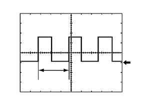
| Item | Condition |
|---|---|
| Tester connection | ·
E17-5 (SI) - Body ground ·
E17-6 (+S) - Body ground |
| Tool setting | 5 V/DIV., 20 ms./DIV. |
| Condition | Ignition switch ON, wheel being rotated |
- HINT:
-
When the system is functioning normally, one wheel revolution generates 4 pulses. As the vehicle speed increases, the width indicated by (A) in the illustration narrows.
| Item | Condition |
|---|---|
|
*: for Gasoline Model |
|
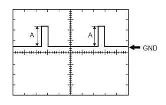
| Tester connection | ·
E17-14 (FR) - E17-33 (FE&B) ·
E17-28 (FR2) - E17-33 (FE&B)* |
| Tool setting | 2.5 V/DIV., 20 ms./DIV. |
| Condition | Ignition switch ON, fuel receiver gauge indicates F → E (fuel level warning light on) |
- HINT:
-
The magnitude of the voltage (A) changes as shown in the following tables.
for HV Model: Terminal No. (Symbol) Condition Specified Condition E17-14 (FR) - E17-33 (FE&B) Ignition switch ON, fuel receiver gauge indicates F 4.2 to 4.6 V Ignition switch ON, fuel receiver gauge indicates E
(fuel level warning light on)0.3 to 1.1 V
for Gasoline Model: Terminal No. (Symbol) Condition Specified Condition E17-28 (FR2) - E17-33 (FE&B) Ignition switch ON, fuel receiver gauge indicates F 3.6 to 4.6 V Ignition switch ON, fuel receiver gauge indicates below 1/2 0.3 to 0.5 V E17-14 (FR) - E17-33 (FE&B) Ignition switch ON, fuel receiver gauge indicates 1/2 or more 4.4 to 4.6 V Ignition switch ON, fuel receiver gauge indicates E
(fuel level warning light on)0.3 to 1.3 V

| Item | Condition |
|---|---|
| Tester connection | E17-15 (FV) - Body ground |
| Tool setting | 2.5 V/DIV., 20 ms./DIV. |
| Condition | Ignition switch ON |
| Specified Condition | 4.5 to 5.5 V |
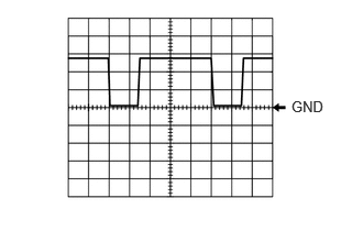
| Item | Condition |
|---|---|
| Tester Connection | E17-34 (LST1) - Body ground |
| Tool setting | 5 V/DIV., 20 ms./DIV. |
| Condition | The following message (interrupt display) being displayed on the multi-information display:
"Ready to Refuel" |
| Item | Condition |
|---|---|
| Tester Connection | E17-34 (LST1) - Body ground |
| Tool setting | 5 V/DIV., 20 ms./DIV. |
| Condition | The following message (interrupt display) being displayed on the multi-information display:
"Close Fuel Lid" |
- HINT:
-
This waveform is output when the fuel lid opener switch is operated if the fuel lid is open and any of the following conditions are met:
- ·
The vehicle has been driven for 1 km (0.6 mile) or more at a speed of 50 km/h (31 mph) or more.
·30 minutes or more have elapsed since the fuel lid opener switch was operated.
| Item | Condition |
|---|---|
| Tester Connection | E17-34 (LST1) - Body ground |
| Tool setting | 5 V/DIV., 20 ms./DIV. |
| Condition | The following message (interrupt display) being displayed on the multi-information display:
"Please Wait Fuel Door Opening" |
- HINT:
-
This waveform is output when the internal pressure of the fuel tank is higher than the ambient pressure when the fuel lid opener switch is operated.
COMBINATION METER ASSEMBLY (Seat Belt Warning System)